

Internal structural lintel is for supporting unit masonry above an opening in a wall
a technology for supporting units and walls, applied in the direction of girders, joists, transoms, etc., can solve the problems of inability to offer substantial resistance, prohibitively large thrust, and simple and efficient true arch
- Summary
- Abstract
- Description
- Claims
- Application Information
AI Technical Summary
Problems solved by technology
Method used
Image

Examples
Embodiment Construction
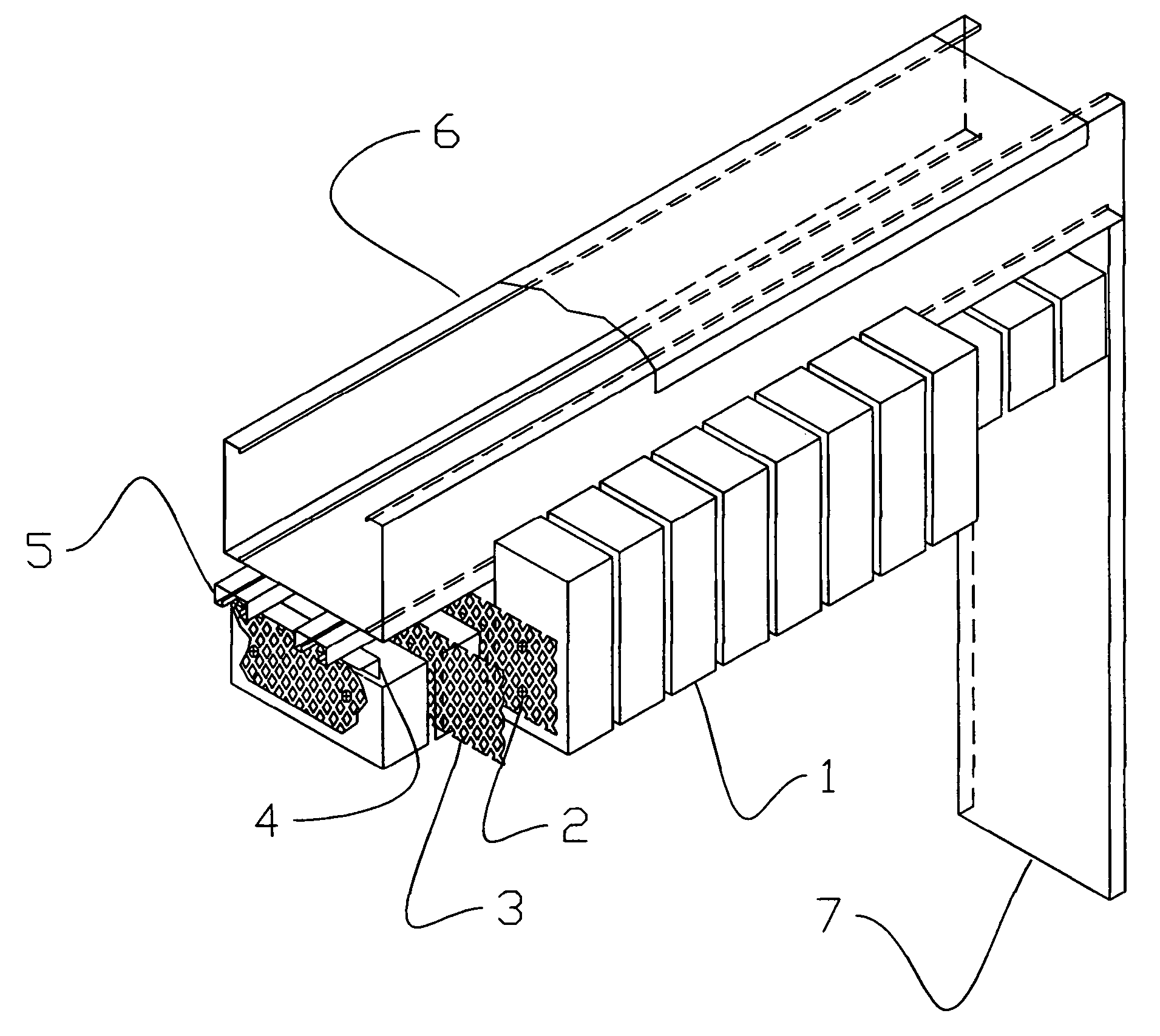
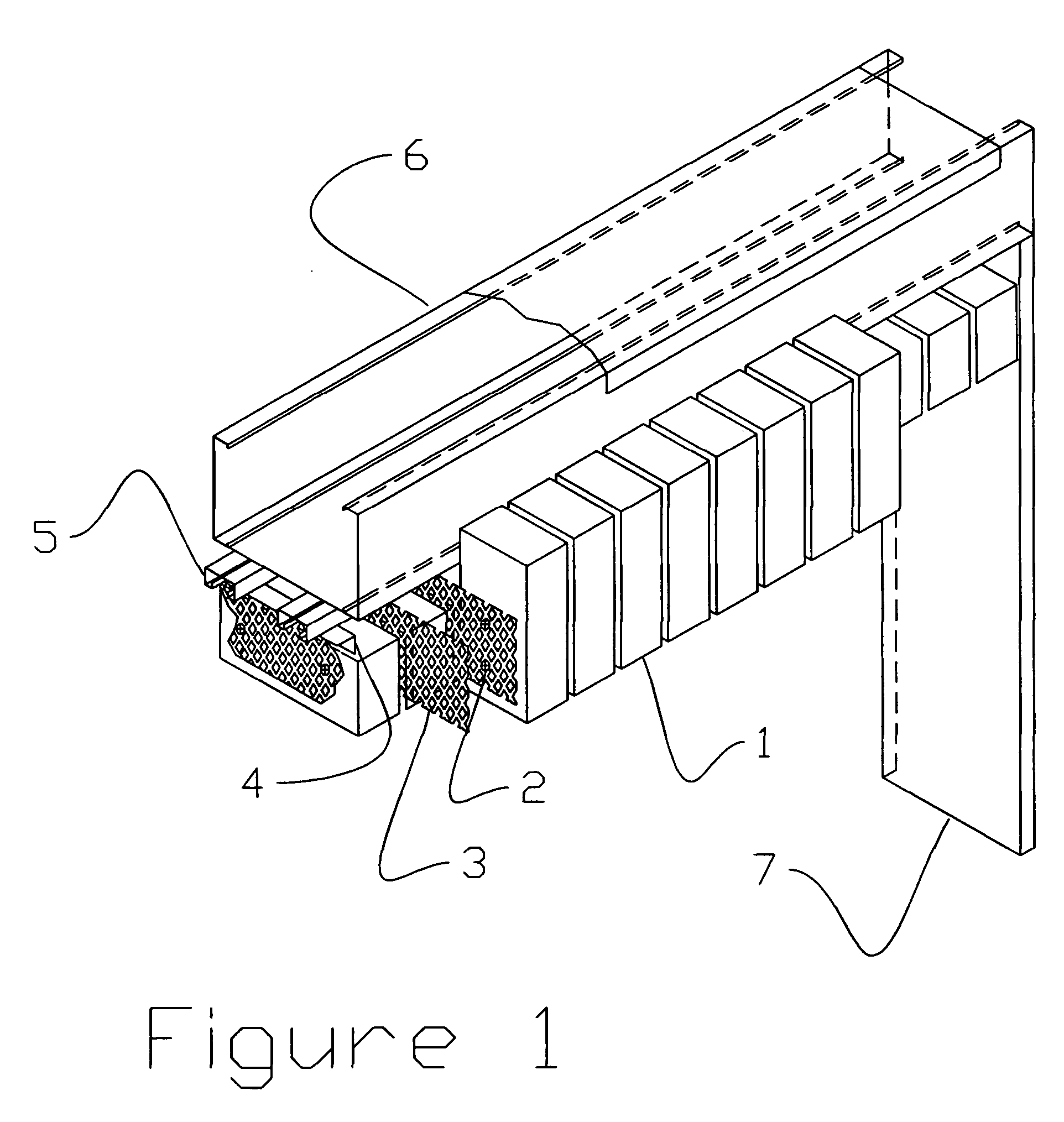
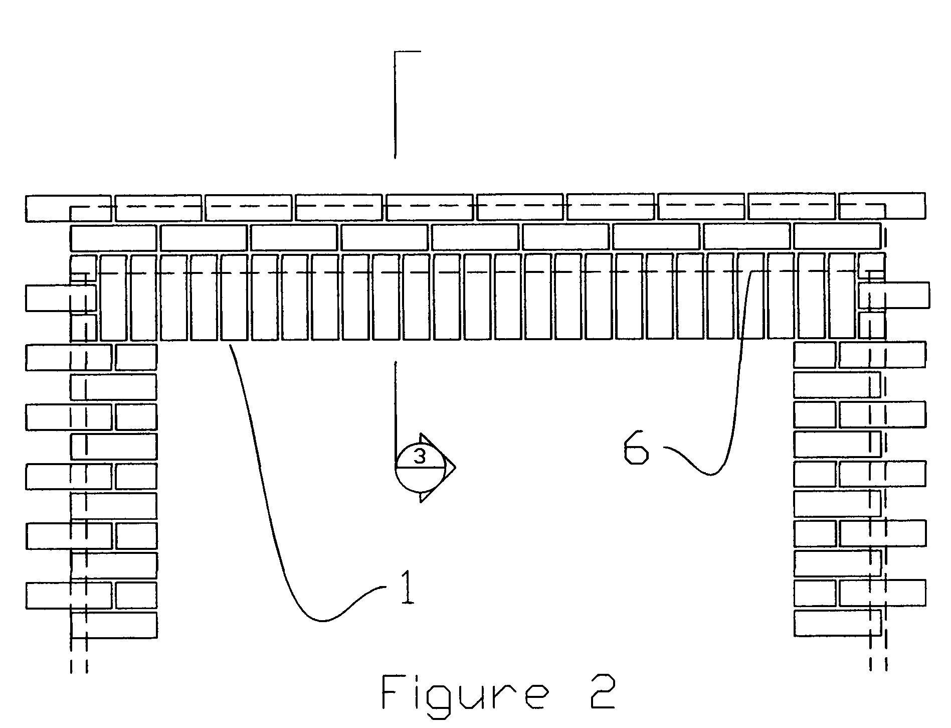
[0025] A masonry unit 1 is attached to a perforated suspension member 3 by means of a mechanical anchor 2. This attachment is made in the field-by the mason building the wall. The perforations in the suspension member allow adjustment in two directions. The suspension member 3 is attached in turn to an attachment angle 4 by means of a welded or mechanical connection. This connection is made in the shop to form an assembly. The attachment angle is fastened to a connection strut 5 using a strut fastener 8. This connection is made in the field by the mason building the wall. The connection strut 5 is attached to a support beam 6 using a series of welded or mechanical connections. These connections are made in the shop to form an assembly. The connection strut is continuous along the length of the support beam. The suspension member 3 can be located anywhere along the support beam 6 allowing adjustment in the third dimension.
PUM
 Abstract
Description
Claims
Application Information