Display tilting apparatus

Active Publication Date: 2005-09-22
FUJITSU FRONTECH LTD
View PDF11 Cites 38 Cited by
  • Summary
  • Abstract
  • Description
  • Claims
  • Application Information

AI Technical Summary

Benefits of technology

[0011] It is an object of the present invention to solve at least the problems in the conventional technology.
[0012] The display tilting apparatus according to one aspect of the present invention includes a moving bracket that supports a display; a ratchet mechanism that controls pivoting of the moving bracket to a first direction; an anti-tilting mechanism that inhibits pivoting of the moving bracket to a second direction that is opposite of the first direction; and a fixed bracket that is pivotably connected to the moving bracket via a pivot axis. The anti-tilting mechanism includes a first anti-tilting member that inhibits pivoting of the moving bracket; and a second anti-tilting member that is mounted on the fixed bracket. The first anti-tilting member and the second anti-tilting member are mounted so as to make

Problems solved by technology

However, the conventional technologies have the following problems in adjusting the angle of the LCD screen.
On the other hand, the tilt-locking function of the ratchet mechanism does not work when the LCD screen 200 tilts to the operator's side, an

Method used


Image

  • Display tilting apparatus
  • Display tilting apparatus
  • Display tilting apparatus

Examples


Example

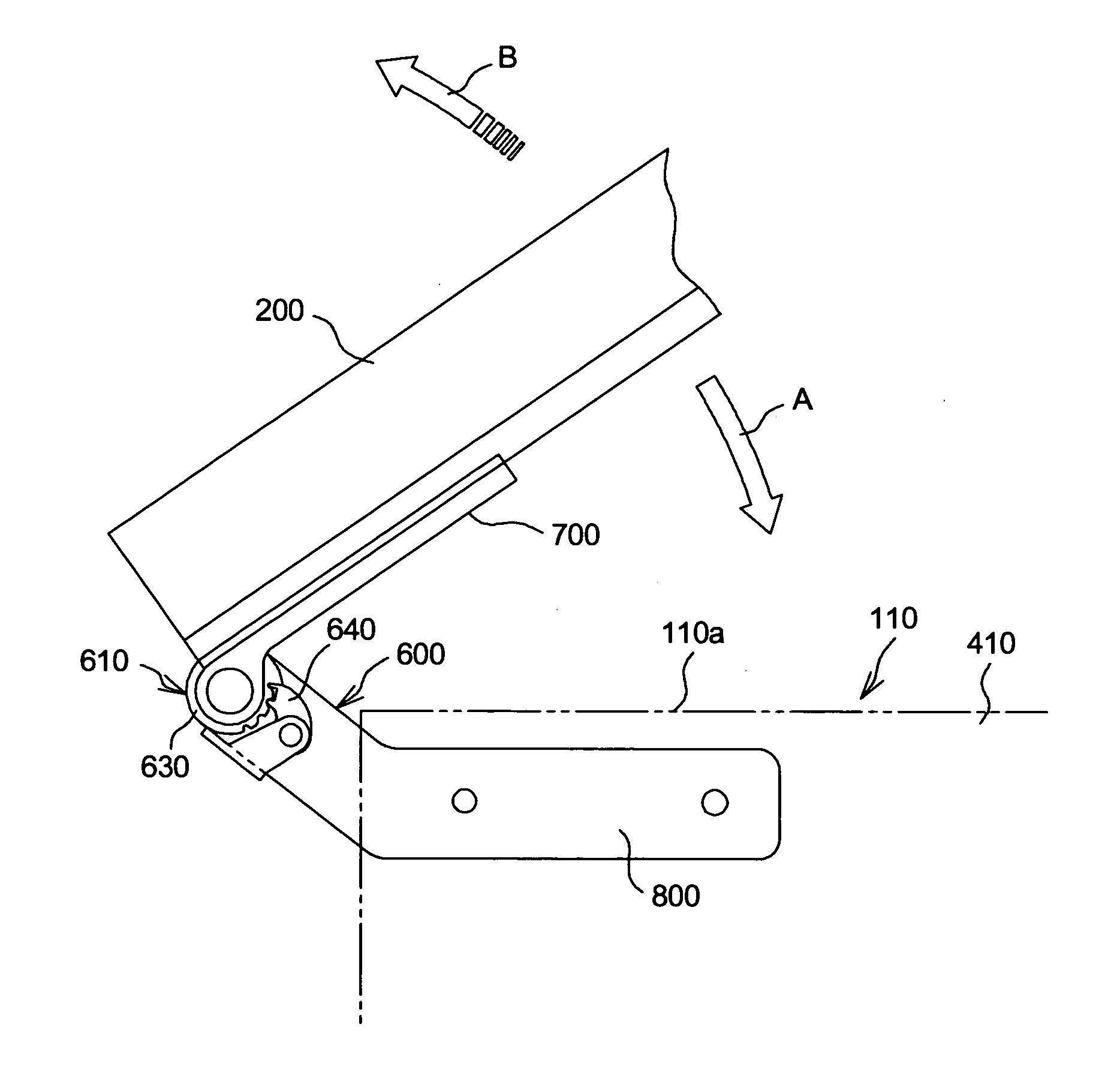
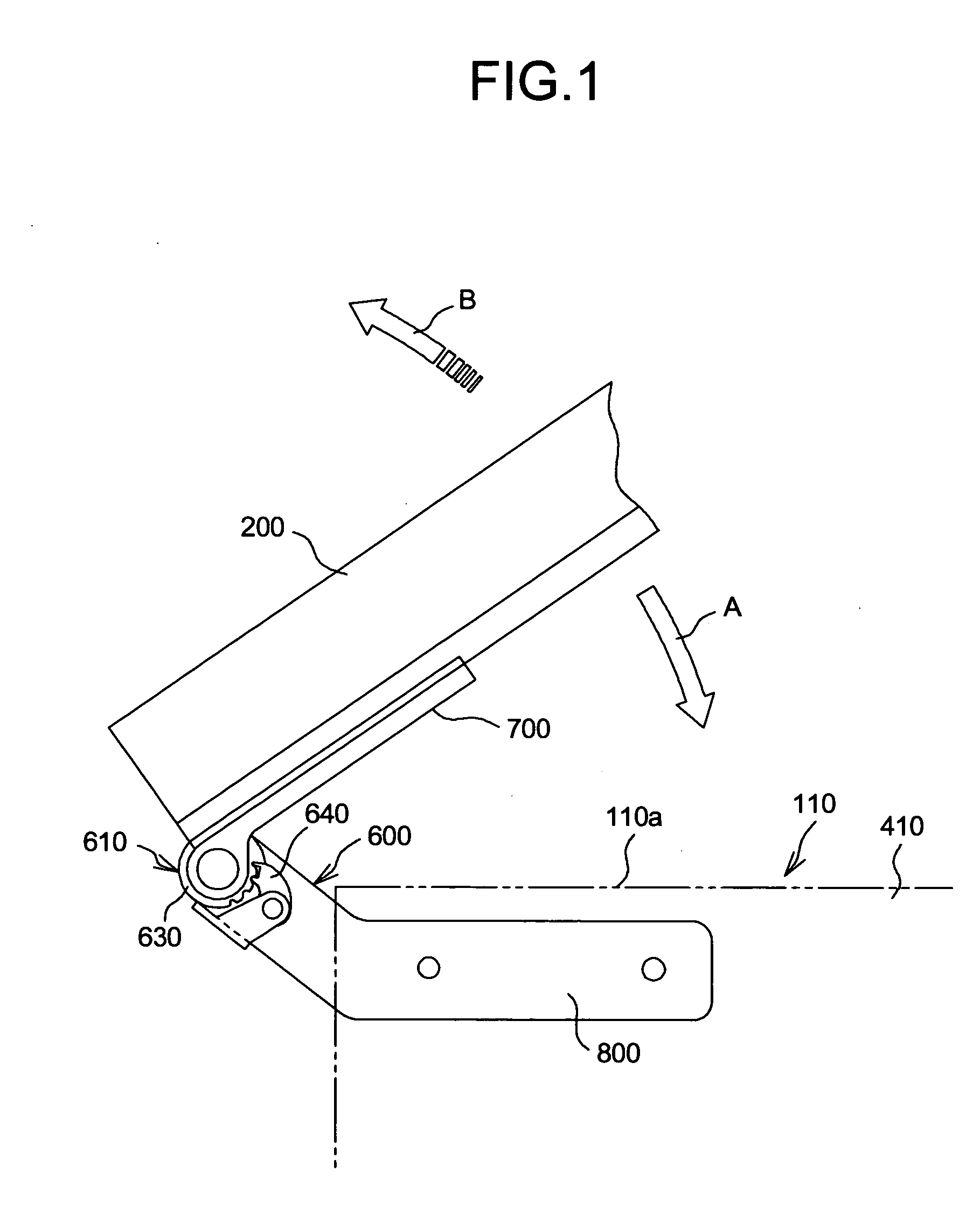
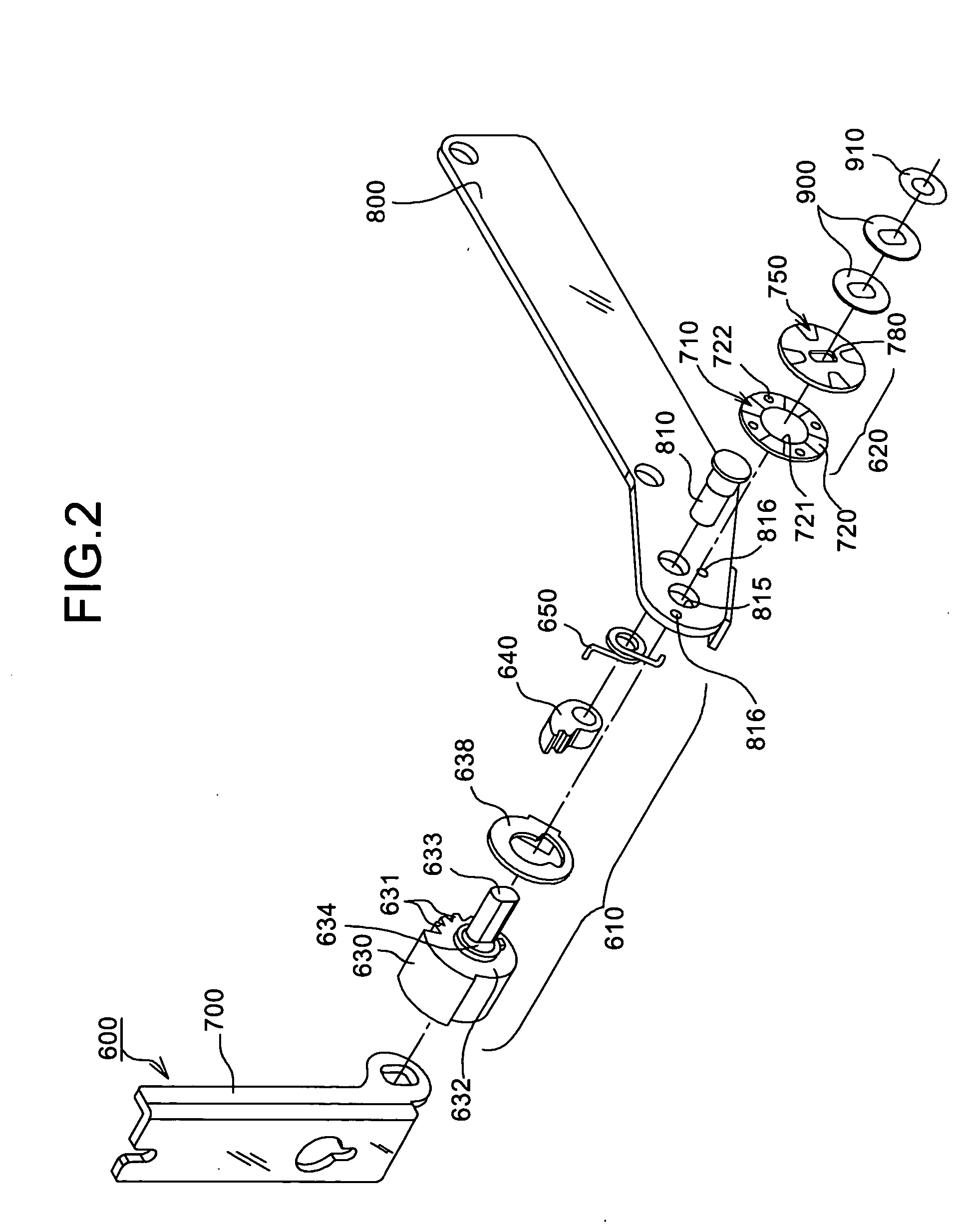
[0030]FIG. 1 is a side view of a display tilting apparatus according to a first embodiment of the present invention. FIG. 2 is an exploded view of the display tilting apparatus. FIG. 3 is a cross-section of main parts of the display tilting apparatus.

[0031] A POS terminal 110 includes the LCD screen 200, on which the operator performs the key-touch operation (for accounting operation), the main body 100a, the printer 300, which prints a printing paper such as a receipt, and a controller 400. The both sides of the LCD screen 200 are fitted with a pair of moving brackets 700 using screws, and a fixed bracket 800, which is connected to an end of the moving bracket 700, is fitted with a side 410 of the main body 100a using screws. A display tilting apparatus 600 according to the present invention is arranged in a connection (a hinge) between the moving bracket 700 and the fixed bracket 800.

[0032] As shown in FIG. 1 and FIG. 2, the display tilting apparatus 600 includes a ratchet mecha...

Example

[0047] In this manner, in the second embodiment, the same effect as the first embodiment is realized, and the cost reduction is realized by reducing the number of the components, namely by omitting the fixed-side anti-tilting plate 710.

[0048] Although the display tilting apparatus is applied to the LCD screen of the POS terminal in the first embodiment and the second embodiment, the present invention is not to be thus limited but may be applied to the panels, for customers, of the commutation-ticket vending machine and the automatic teller machine (ATM) of the bank and the like.

[0049] As stated above, the display tilting apparatus according to the present invention is useful in adjusting the angle of the LCD screen, and especially, suitable for adjusting the angle of the LCD screen of the information-display apparatus, such as the POS terminal.

[0050] Consequently, the effect of the present invention is that the angle of the LCD screen to the operator's side can be adjusted to any...


PUM


Abstract

A display tilting apparatus includes a moving bracket that supports a display, a ratchet mechanism that controls pivoting of the moving bracket to a first direction, an anti-tilting mechanism that inhibits pivoting of the moving bracket to a second direction that is opposite of the first direction, and a fixed bracket that is pivotably connected to the moving bracket via a pivot axis. The anti-tilting mechanism includes a first anti-tilting member, and a second anti-tilting member that is mounted on the fixed bracket. The first anti-tilting member and the second anti-tilting member are mounted so as to make a physical contact to each other.

Description

BACKGROUND OF THE INVENTION [0001] 1) Field of the Invention [0002] The present invention relates to a technology for adjusting an angle of a liquid-crystal display (LCD) screen to improve operationality and safety by using a tilt-locking function of a ratchet mechanism and a anti-tilting function of an anti-tilting mechanism. [0003] 2) Description of the Related Art [0004] Point-of-sales (POS) terminals are widely used in department stores and the restaurants as an information-display apparatus having an LCD screen. FIG. 8A and FIG. 8B are a perspective view and a side view of a conventional POS terminal 100, respectively. The POS terminal 100 includes an LCD screen 200, on which the operator performs the key-touch operation (for accounting operation or the like), a main body 100a, a printer 300, which prints a printing paper such as a receipt, and a controller 400. A receipt exit 500 is used to issue the receipts that the printer 300 prints. [0005] A hinge 550 connects the LCD scr...

Claims


Application Information

Patent Timeline
IPC IPC(8): F16C11/10E04G3/00F16C11/00F16M11/10G02F1/13G07G1/00G09F9/00G11B33/02G12B9/00
CPCE05D11/105E05D11/1078E05Y2201/216E05Y2201/234E05Y2900/606Y10T16/540345F16M13/02F16M2200/024F16M2200/041G07G1/0018F16M11/10G11B33/02
Inventor ICHIKAWA, TOSHIYUKIMIYAZAWA, KENICHIISHII, NOBORUYOSHIDA, TAKUMANISHIOKA, SATOSHI
Owner FUJITSU FRONTECH LTD
Why Eureka
Try Eureka