
Print-item setting server apparatus, print-item setting method, and computer program product

Inactive Publication Date: 2009-09-10
RICOH KK
View PDF5 Cites 57 Cited by
  • Summary
  • Abstract
  • Description
  • Claims
  • Application Information

AI Technical Summary

Benefits of technology

[0008]It is an object of the present invention to at least partially solve the problems in the conventional technology.

Problems solved by technology

Therefore, setting items are uniformly arranged in the print setting screen which makes improvement in the usability, for example, changing the layout of the print setting screen depending on the document to be printed, difficult.
In the technology described in Japanese Patent Application Laid-open No. 2006-74601, although a print setting screen can be changed separately for each client device, it is not possible to change a print setting screen integrally for two or more client devices.

Method used


Image

  • Print-item setting server apparatus, print-item setting method, and computer program product
  • Print-item setting server apparatus, print-item setting method, and computer program product
  • Print-item setting server apparatus, print-item setting method, and computer program product

Examples


first embodiment

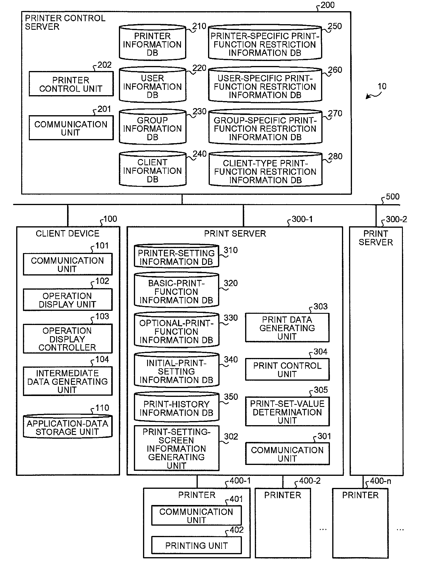
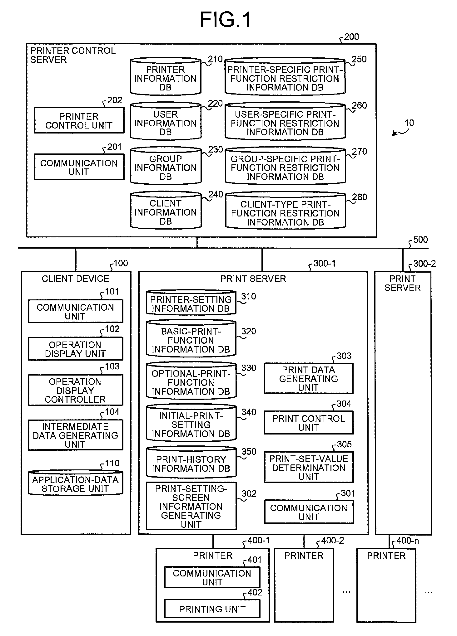
[0039]FIG. 1 is a block diagram of a printing system 10 according to the present invention.

[0040]The printing system 10 includes a client device 100, a printer control server 200, print servers 300-1 and 300-2 (hereinafter, “print server 300”), and printers 400-1, 400-2, . . . 400-n (hereinafter, “printer 400”). An arbitrary one of the print servers 300-1 and 300-2 will be referred to as a print server 300, and arbitrary one of the printers 400-1, 400-2, . . . 400-n will be referred to as a printer 400″. The client device 100, the printer control server 200, and the print server 300 are connected to each other through a network 500. The print server 300 and the printer 400 may be connected to each other with a cable or the like, or may be connected to each other with a network such as a local area network (LAN). Although the printer control server 200 and the print server 300 are illustrated as separate devices, then may be integrated in one device.

[0041]Although only one client dev...

second embodiment

[0102]FIG. 23 is a block diagram of a printing system 20 according to the The printing system 20 includes a client device 1100, a data server 1700, a control server 1600, a printer control server 1200, print servers 1300-1 and 1300-2 (hereinafter, “print server 1300”), and the printer 400. The client device 1100, the data server 1700, the control server 1600, the printer control server 1200, and the print server 1300 are connected to each other through the network 500. The print server 1300 and the printer 400 may be connected to each other through the cable or the like, or may be connected through a network such as LAN.

[0103]The client device 1100 includes the communication unit 101, the operation display unit 102, and the operation display controller 103. The configuration and functions of these components with the same reference numerals as these of the first embodiment are identical to these of the first embodiment, and thus, explanation thereof is omitted. Hereafter, when the ...


PUM


Abstract

A print server receives a transmission request and a printer ID from a client device, acquires print function information corresponding to the printer ID from print-function information DBs, and acquires function restriction information from a function-restriction information DB of a printer control server. The print server then generates setting screen information based on the print function information and the function restriction information, and transmits the setting screen information to the client device. The client device receives the setting screen information, and creates and displays a setting screen by using the setting screen information.

Description

CROSS-REFERENCE TO RELATED APPLICATIONS[0001]The present application claims priority to and incorporates by reference the entire contents of Japanese priority document 2008-060158 filed in Japan on Mar. 10, 2008.BACKGROUND OF THE INVENTION[0002]1. Field of the Invention[0003]The present invention relates to a print-item setting server apparatus, a print-item setting method, and a computer program product.[0004]2. Description of the Related Art[0005]Conventionally, when document data is to be printed from a client device in a document management system built in offices, there is generally known a technology of generating print data based on set values for various setting items selected from a print setting screen and printing (outputting) the generated print data with a printer. The print setting screen is displayed on a display device of the client device is provided as a function of a printer driver which corresponds to the printer. Therefore, setting items are uniformly arranged i...

Claims


Application Information

Patent Timeline
IPC IPC(8): G06F3/12
CPCG06F3/1204G06F3/1285G06F3/1232G06F3/1228
Inventor EMORI, MOTOTSUGU
Owner RICOH KK
Learn More