However, it is difficult to completely eliminate the speed fluctuation of the
direct transfer conveying belt or intermediate transfer conveying belt although it can be reduced by means of
feedback control.
However, this method causes changes in conveying speed of the transfer sheet or the intermediate transfer conveying belt due to a minute thickness of the endless belt, and causes lowering in
image quality such as image deviation from an ideal position and positional displacement of an image among a plurality of recording sheets, resulting in deteriorated repetitive image position reproducibility among recording sheets.
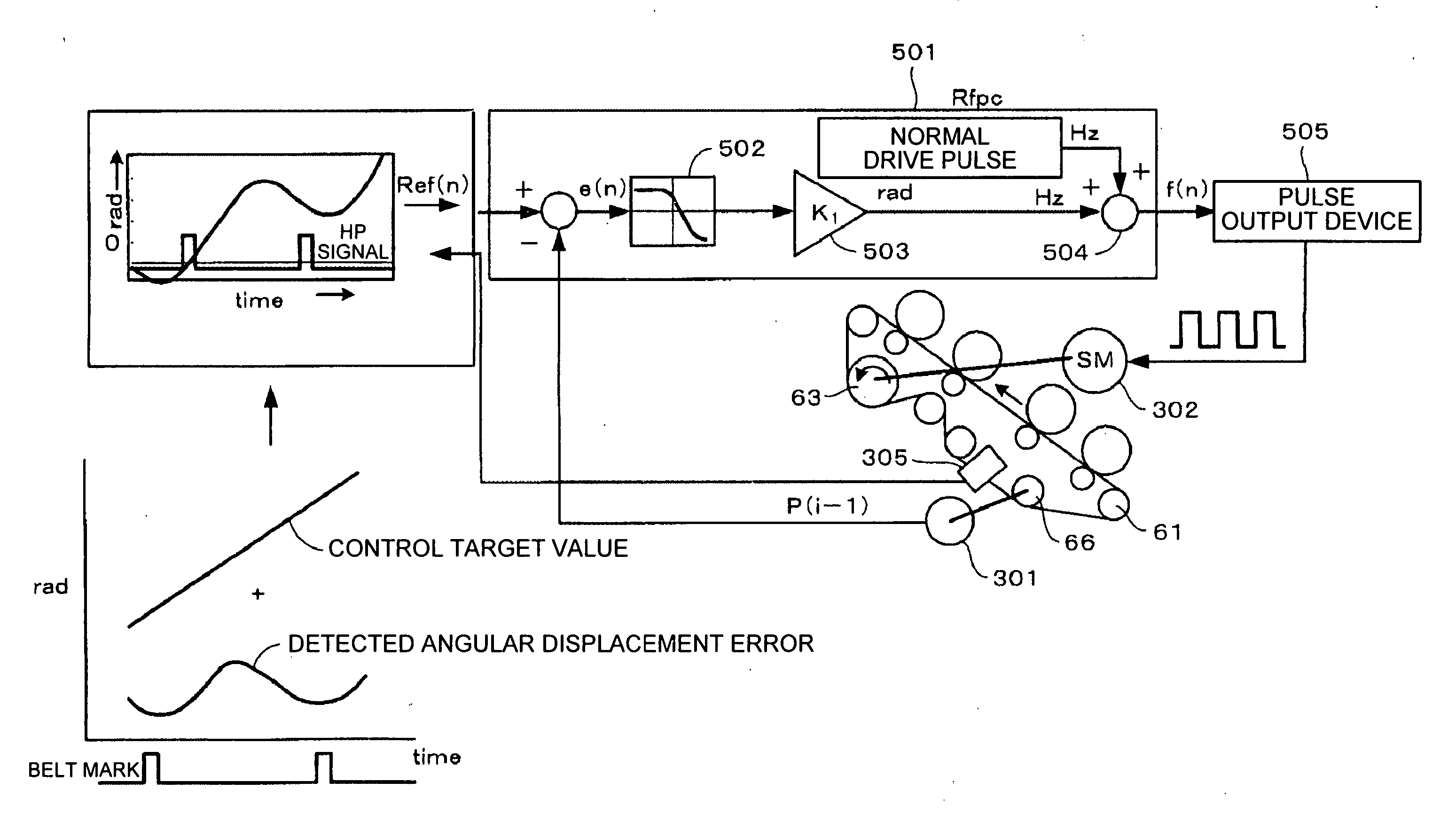
When the belt thickness fluctuation occurs and the belt conveying speed is detected by the
encoder based on the rotation
angular displacement of the follower shaft, erroneous detection components are generated.
Therefore, in
feedback control to detect the belt conveying speed based on the follower shaft rotation
angular displacement as conventionally, the speed fluctuation due to fluctuation in thickness of the belt cannot be controlled.
However, in the above method, as speed profile data, data for each control cycle is needed, so that when the control cycle is short, a memory with a high capacity becomes necessary, and when the control cycle is set long, feedback control itself cannot show a sufficient effect.
Therefore, a separate memory is necessary in addition to the memory that has been used as a normal work area, and this results in a remarkable cost increase and is not realistic.
However, to measure the thickness fluctuation of several micrometers of the belt, a high-accuracy measuring unit is necessary, and
data management and data amount of the measured results are large in size, and this may cause an input error.
In the color-shift detecting device, since speed fluctuation of the belt due to belt thickness fluctuation cannot be controlled by means of feedback control in that the belt conveying speed is detected based on the conventional follower shaft rotation angular displacement, the fluctuation harmfully influences the
color shift correction accuracies and causes image deterioration.
Namely, the
belt speed when mark sets for
color shift correction are drawn on the belt and the
belt speed when the mark sets are detected are different from the
belt speed when images are actually drawn on the belt, resulting in color shifts.
However, in this case, the length of all groups of mark sets may become long, the
color shift correction time may become slightly long, or the toner consumption may slightly increase.
Furthermore, if the execution timing of color shift detection and correction is only either one of an execution timing instructed through an operation panel or an automatic execution timing,
image quality that a customer desires cannot be provided in a desired timing in some cases.
However, if calculation of the phase and
maximum amplitude to be stored in the nonvolatile memory is performed by only either one of manual execution or automatic execution, in some cases,
image quality that a customer desires cannot be provided in a desired timing.
Particularly, when the phase and
maximum amplitude of the angular
displacement error change due to aging of the belt, color shift detection and correction makes worse the color shifts unless the calculation is performed.

