Image forming apparatus

Active Publication Date: 2012-04-26
RICOH KK
View PDF13 Cites 58 Cited by
  • Summary
  • Abstract
  • Description
  • Claims
  • Application Information

AI Technical Summary

Benefits of technology

[0014]It is an object of the present invention to at least

Problems solved by technology

In recent years, there are demands for the high image quality, and conventional methods are difficult to suppress the density v

Method used


Image

  • Image forming apparatus
  • Image forming apparatus
  • Image forming apparatus

Examples


first embodiment

First Embodiment (1)

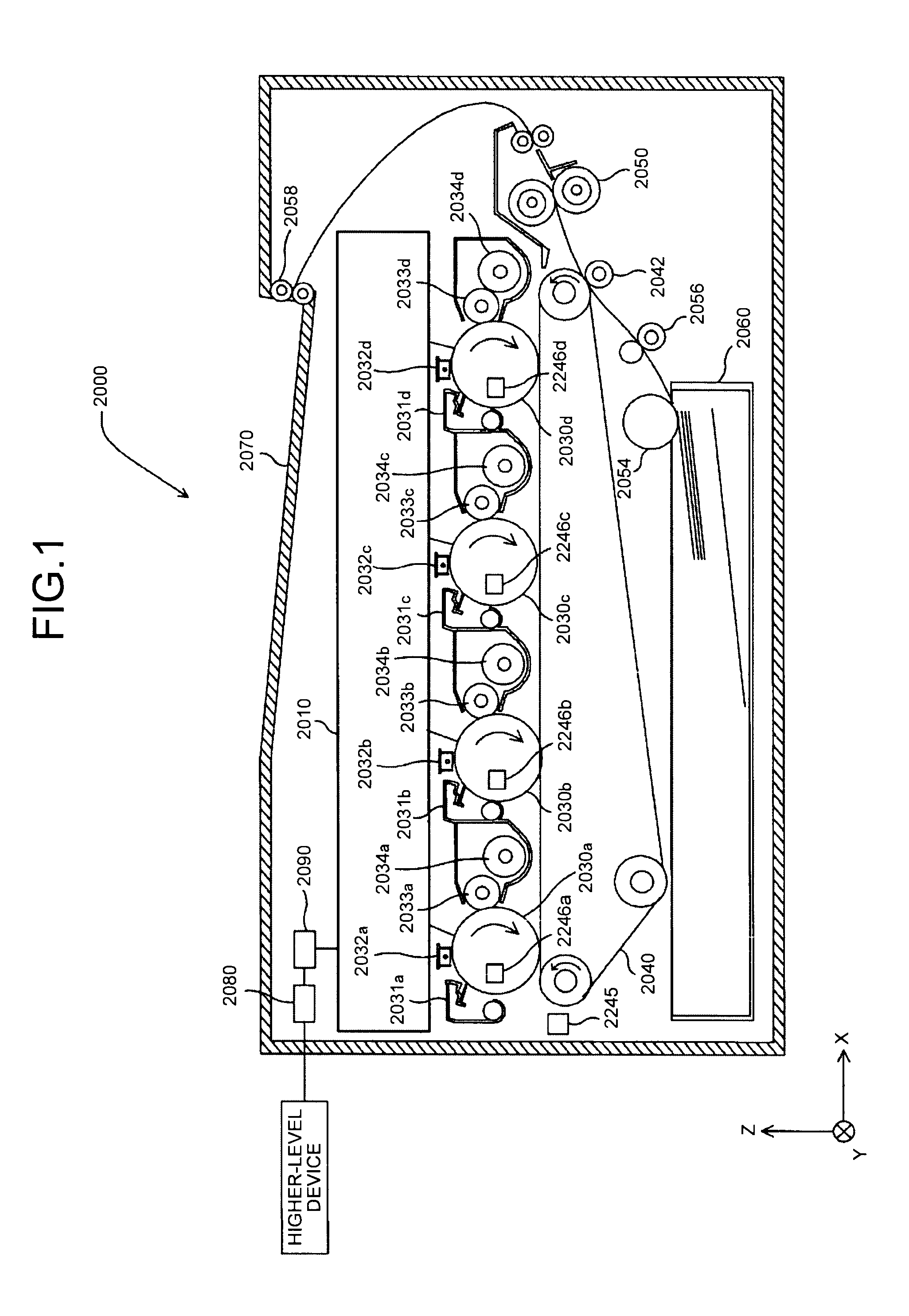
[0097]A first embodiment (1) will be described below with reference to FIGS. 1 to 24. FIG. 1 illustrates a schematic configuration of a color printer 2000 as an image forming apparatus according to the first embodiment (1).

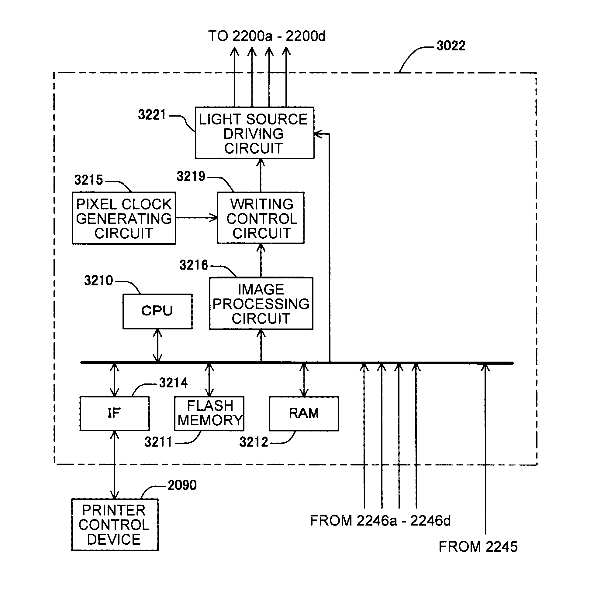
[0098]The color printer 2000 is a tandem type multi-color printer that forms a full-color image by superimposing four colors (black, cyan, magenta, and yellow). The color printer 2000 includes an optical scanning device 2010, four photosensitive elements 2030a, 2030b, 2030c, and 2030d, four cleaning units 2031a, 2031b, 2031c, and 2031d, four charging units 2032a, 2032b, 2032c, and 2032d, four developing rollers 2033a, 2033b, 2033c, and 2033d, four toner cartridges 2034a, 2034b, 2034c, and 2034d, a transfer belt 2040, a transfer roller 2042, a fixing roller 2050, a paper feeding roller 2054, a pair of registration rollers 2056, a discharging roller 2058, a paper feed tray 2060, a discharge tray 2070, a communication control device 2080, a densit...

first embodiment (

2)

[0210]A first embodiment (2) will be described below with reference to FIGS. 38 to 41. A color printer 2000A according to the first embodiment (2) has a feature of including a paper leading edge detecting sensor 2247 as illustrated in FIG. 38. The remaining configuration is the same as in the first embodiment (1). Thus, the following description will be made focusing on a difference point from the first embodiment (1). Components identical or equivalent to the first embodiment (1) will be denoted by the same reference numerals, and a description thereof will be simplified or will not be redundantly repeated.

[0211]Meanwhile, there is a phenomenon (hereinafter, referred to as a “thick leading edge”) that a density deviation band corresponding to the length of one period of the developing roller is generated, in a leading edge of an image directly after an image pattern is switched, at a position where the image pattern is switched due to one of the density variations in the sub scan...

second embodiment

Second Embodiment (1)

[0242]Next, a description will be made in connection with a second embodiment (1). A color printer according to the second embodiment (1) is the same as in FIG. 1, a configuration of the optical scanning device is the same as in FIGS. 4 to 7, and thus a redundant description thereof will not be repeated. In the second embodiment, the same drawings and the same reference numerals are used for the same drawings as in the first embodiment, and a redundant description thereof will not be repeated. A description will be made in connection with different portions.

[0243]The second embodiment (1) is different from the first embodiment in that three density detectors are disposed in the main scanning direction as illustrated in FIG. 42.

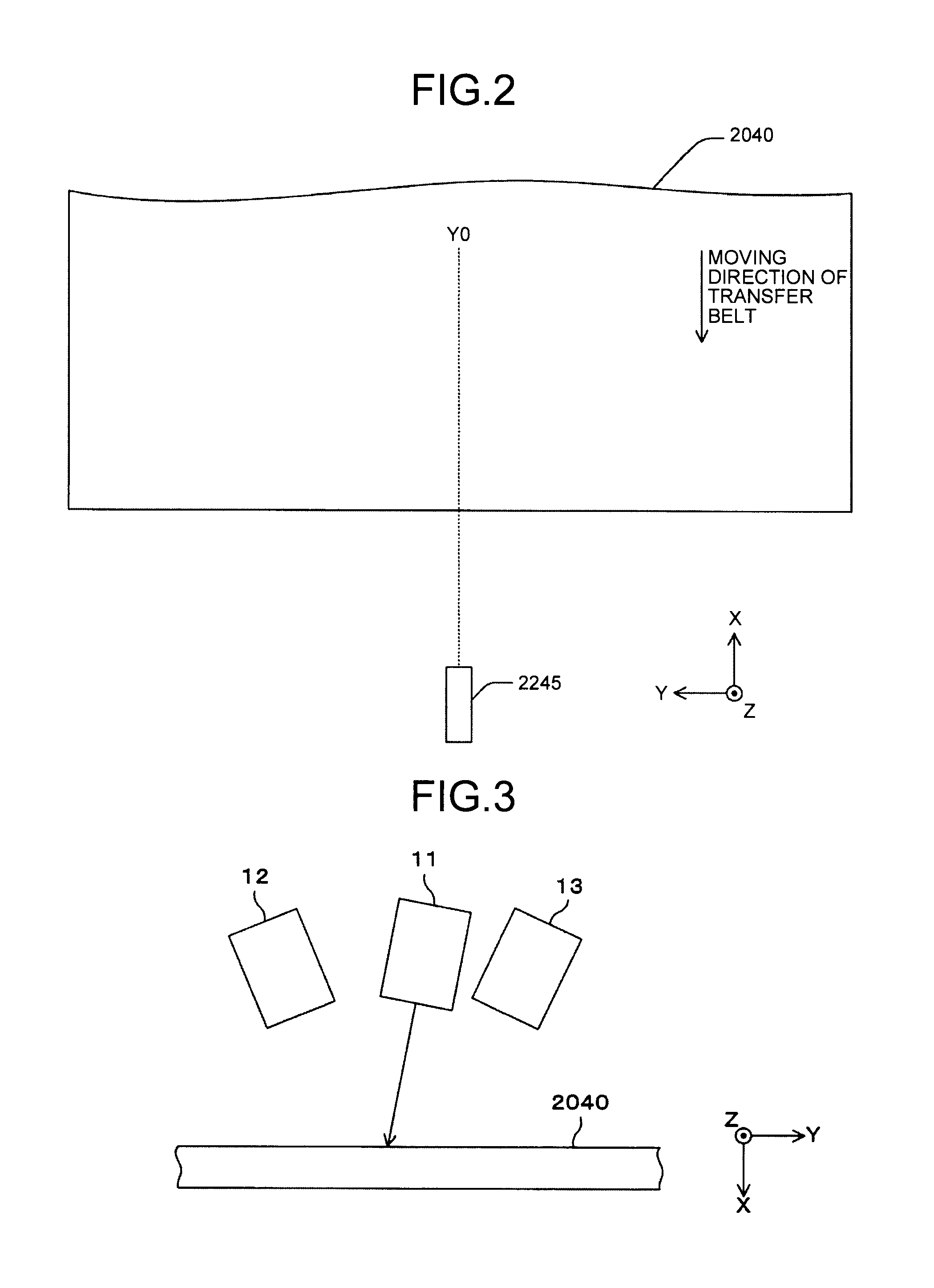
[0244]The density detector 2245 is arranged at the −X side of the transfer belt 2040. The density detectors 2245 includes three optical sensors 2245a, 2245b, and 2245c as illustrated in FIG. 42 as an example.

[0245]The optical sensor 2245a ...


PUM


Abstract

An image forming apparatus that forms an image includes: a photosensitive element; an optical scanning device that includes a light source, and scans a surface of the photosensitive element in a main scanning direction with light emitted from the light source to form a latent image; a developing unit that develops the latent image; a photosensitive element period detecting sensor that detects a rotation period of the photosensitive element; a density sensor that detects a density variation of an image developed by the developing unit, in a sub scanning direction; and a processing device that corrects a driving signal of the light source according to the image information, based on an output signal of the density sensor and an output signal of the photosensitive element period detecting sensor.

Description

CROSS-REFERENCE TO RELATED APPLICATIONS[0001]The present application claims priority to and incorporates by reference the entire contents of Japanese Patent Application No. 2010-235042 filed in Japan on Oct. 20, 2010, Japanese Patent Application No. 2010-235058 filed in Japan on Oct. 20, 2010, and Japanese Patent Application No. 2011-047171 filed in Japan on Mar. 4, 2011.BACKGROUND OF THE INVENTION[0002]1. Field of the Invention[0003]The present invention relates to an image forming apparatus, and more particularly, to an image forming apparatus using laser light.[0004]2. Description of the Related Art[0005]In an image forming apparatus such as a laser printer, a digital copying machine, or a facsimile, it is general that light flux scans a scanning target surface while irradiating the scanning target surface so that a latent image is formed on the scanned surface.[0006]The image forming apparatus includes a photosensitive element being photosensitive and serving as a scanned surfac...

Claims


Application Information

Patent Timeline
IPC IPC(8): H04N1/04
CPCH04N1/12G03G15/5058H04N1/0473H04N1/506H04N2201/0471H04N2201/04781H04N2201/04793
Inventor OMORI, ATSUFUMIISHIDA, MASAAKINIHEI, YASUHIROIWATA, MUNEAKI
Owner RICOH KK
Why Eureka
Try Eureka