
Guided retractor and methods of use

a retractor and guide technology, applied in the field of surgical retractors, can solve the problems of insufficient retraction, insufficient retraction, and inability to easily fix the above-mentioned retractors in position relative to one or more bones, and achieve the effect of reducing and increasing the number of retractors

Active Publication Date: 2005-09-29
SYNTHES USA
View PDF78 Cites 72 Cited by
  • Summary
  • Abstract
  • Description
  • Claims
  • Application Information

AI Technical Summary

Benefits of technology

"The present invention provides a surgical retractor with multiple tissue-retaining walls that are mechanically coupled and guided into position. The walls can be opened and closed to create an operating space, and the retractor is particularly useful for operating on curved bones. The guides are implanted into bones and the retractor has oversize channels to receive the guides. The walls can be moved apart using a wedge or other mechanism, and the retractor can be transparent to aid in surgeon visualization. The invention provides a convenient and effective tool for surgical procedures."

Problems solved by technology

While undoubtedly useful in many respects, none of the above-mentioned retractors are readily fixed in position relative to one or more bones.
A problem remains, however, in that the resection required to properly position the retractor can cause considerable trauma to the overlying and surrounding tissues.
Another problem is that multiple retractors are needed to retain tissue pushing into the operating area from different directions.
In spinal and some other surgeries these problems can be especially severe.

Method used


Image

  • Guided retractor and methods of use
  • Guided retractor and methods of use
  • Guided retractor and methods of use

Examples


Embodiment Construction

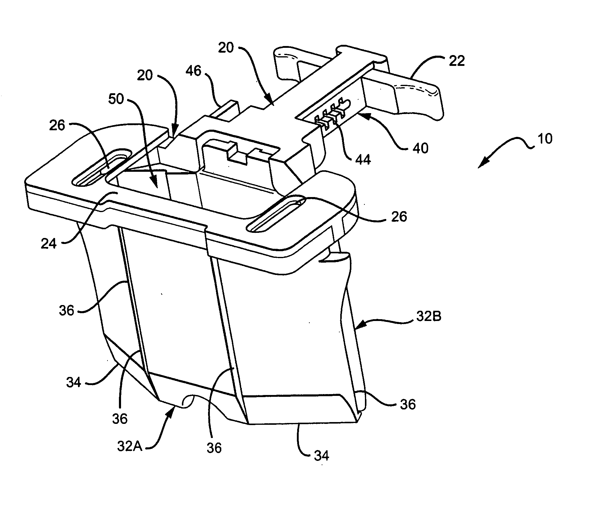
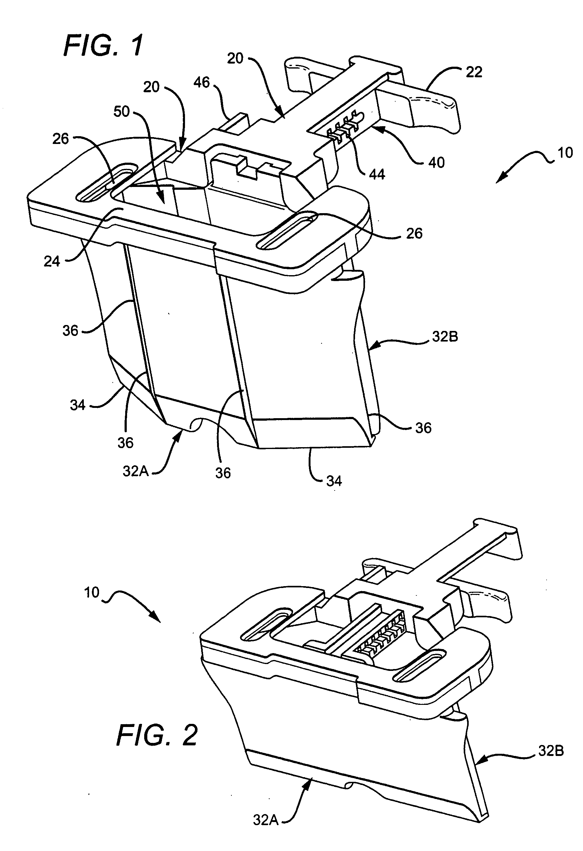
[0052]FIG. 1 generally depicts a retractor 10, having a frame 20, major walls 32A, 32B and minor walls 34, and a locking / opening mechanism 40. The various walls 32A, 32B, 34 are coupled by six hinges 36, and in the open position depicted in the figure cooperate to define an operating space 50.

[0053] The frame 20 can be any suitable size and shape according to the particular applications, with larger frames being generally more useful for larger incisions. For posterior lumber surgery on adult humans, the overall dimensions of an especially preferred frame are about 5.5 cm in depth, 3.5 cm in length, 3 cm in width. Frame 20 is preferably made from Delrin®, but can be made of any suitable material, especially a nontoxic polymer such as polyethylene. The frame 20 can advantageously be colored to reduce glare from operating room lighting, and some or all of the frame can be relatively transparent.

[0054] Frame 20 generally comprises a handle portion 22 that includes the locking mechani...


PUM


Abstract

The present invention provides methods and apparatus in which a surgical retractor comprises a plurality of mechanically coupled tissue retaining walls that are guided into position along one or more guides previously implanted into the patient. The walls are preferably coupled by pivots, so that separating some of the walls from one another opens an operating space. There are preferably two guides, which are driven or screwed into the pedicles of vertebrae, or other bone. Oversized channels are best disposed in a frame, which also serves to hold lock the walls apart. Various convenience features are contemplated including a web disposed between the walls, which expands as the walls are separated. Also contemplated are projections from near the bottoms of one or more of the walls, which can alternatively or additionally help to hold the underlying tissue in place.

Description

CROSS-REFERENCE TO RELATED APPLICATIONS [0001] This application is a Continuation Application of U.S. Provisional Application Ser. No. 60 / 525,732, filed Nov. 26, 2003, the contents of which are incorporated by reference herein.FIELD OF THE INVENTION [0002] The field of the invention is surgical retractors. BACKGROUND OF THE INVENTION [0003] Many types of surgical retractors are known. The simplest devices are tubular probes, or probes adapted with a paddle or other somewhat flatter surface. Recent embodiments of that concept are depicted in U.S. Pat. No. 6,206,826 to Mathews et al. (March 2001). More complicated retractors utilize scissors, bow string, or screw-jack expanders that operate against mating paddles. Those retractors have the advantage of being able to lock the paddles in place, leaving at least one of the surgeon's hands free for other actions. See e.g., U.S. Pat. No. 6,471,644 to Sidor (October 2002). Still other retractors are self opening, including Cosgrove et al., ...

Claims


Application Information

Patent Timeline
Patent Type & Authority Applications(United States)
IPC IPC(8): A61BA61B1/32A61B17/00A61B17/02A61B17/34A61B17/86
CPCA61B1/32A61B17/02A61B17/3439A61B2017/0256A61B2017/00407A61B2017/00862A61B17/86A61B17/00A61B17/56A61B17/88
Inventor LARSON, JEFFREYBERTELE, THEODOREGREENBERG, LOUISSCHORER, SCOTT
Owner SYNTHES USA
Learn More