Mapping method for encoded bits using LDPC code, transmitting and receiving apparatuses employing this method, and program for executing this method

a mapping method and encoded bit technology, applied in the field of digital radio communication, can solve the problems of reducing the error rate characteristic of decoding encoded digital information, not always sufficiently utilizing the characteristics of ldpc codes, and not always sufficiently exhibiting their characteristics

Inactive Publication Date: 2005-09-29
KK TOSHIBA
View PDF14 Cites 101 Cited by
  • Summary
  • Abstract
  • Description
  • Claims
  • Application Information

AI Technical Summary

Benefits of technology

[0009] According to a first aspect of the invention, there is provided a method for mapping of coded bits using a low density parity check (LDPC) code, comprises encoding information bits by using the LDPC code to generate coded bits; sorting the coded bits in accordance with degrees of variable nodes represented by a parity check matrix of the LDPC code; dividing the sorted coded bits into a plurality of groups in accordance with a using modulation scheme; and mapping the coded bits to respective modulation signal points by considering an error resistance of each of the groups and an error resistance of a corresponding one of the modulation signal points.

Problems solved by technology

If portions exhibiting high resistance to bit errors continue, this may well degrade the error rate characteristic when decoding encoded digital information.
Therefore, simply by dispersing the non-uniform error resistance at modulation signal points, the characteristics of LDPC codes are not always sufficiently utilized.
However, if an LDPC code exhibiting different resistances to errors is employed for a coded bit sequence, it does not sufficiently exhibit its characteristics.
Furthermore, also when an LDPC encoder is constructed, no consideration is given to error resistances in a communication channel, therefore LDPC codes used in the LDPC encoder are not always suitable for the characteristics of the communication channel.

Method used


Image

  • Mapping method for encoded bits using LDPC code, transmitting and receiving apparatuses employing this method, and program for executing this method
  • Mapping method for encoded bits using LDPC code, transmitting and receiving apparatuses employing this method, and program for executing this method
  • Mapping method for encoded bits using LDPC code, transmitting and receiving apparatuses employing this method, and program for executing this method

Examples


first embodiment

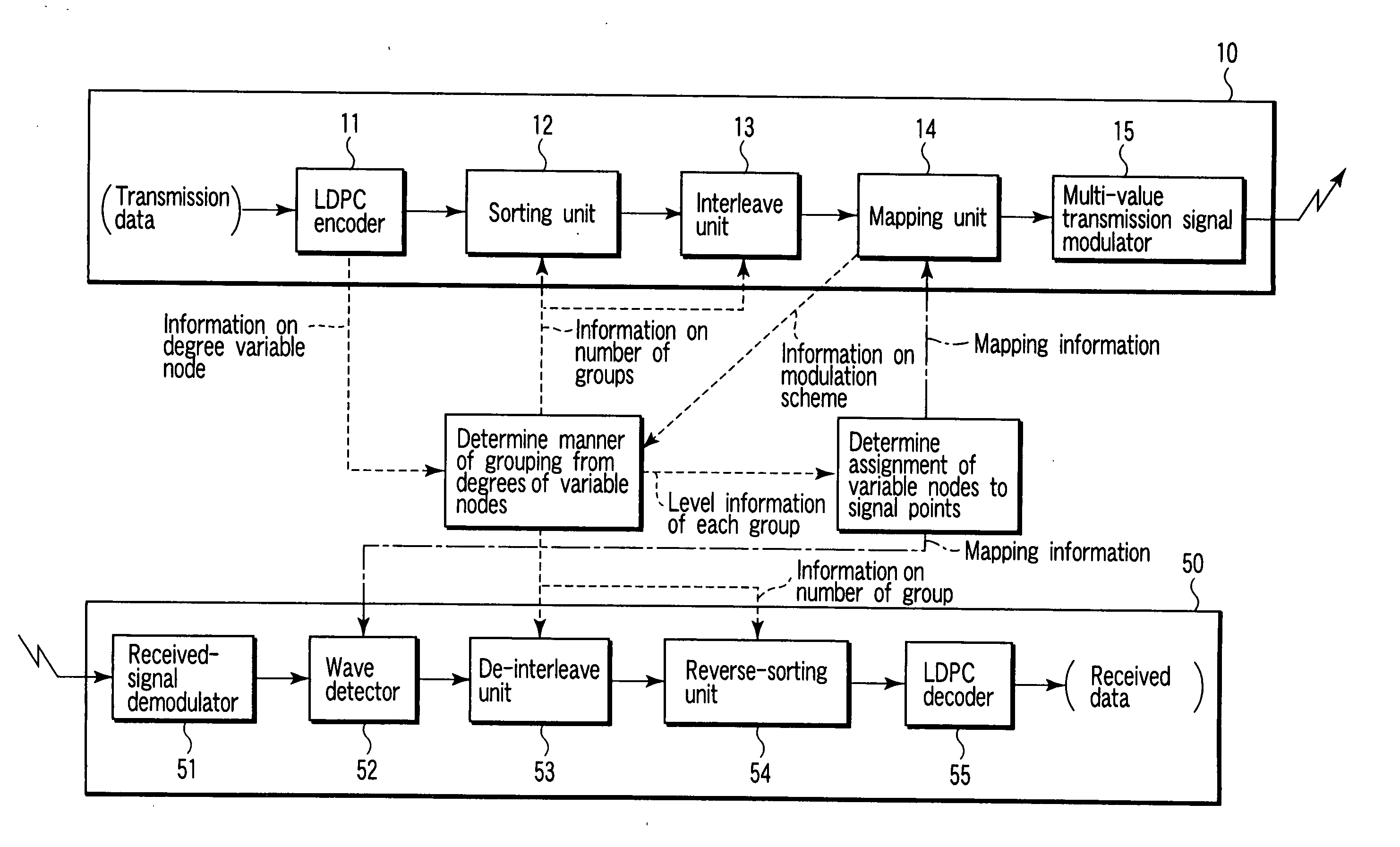
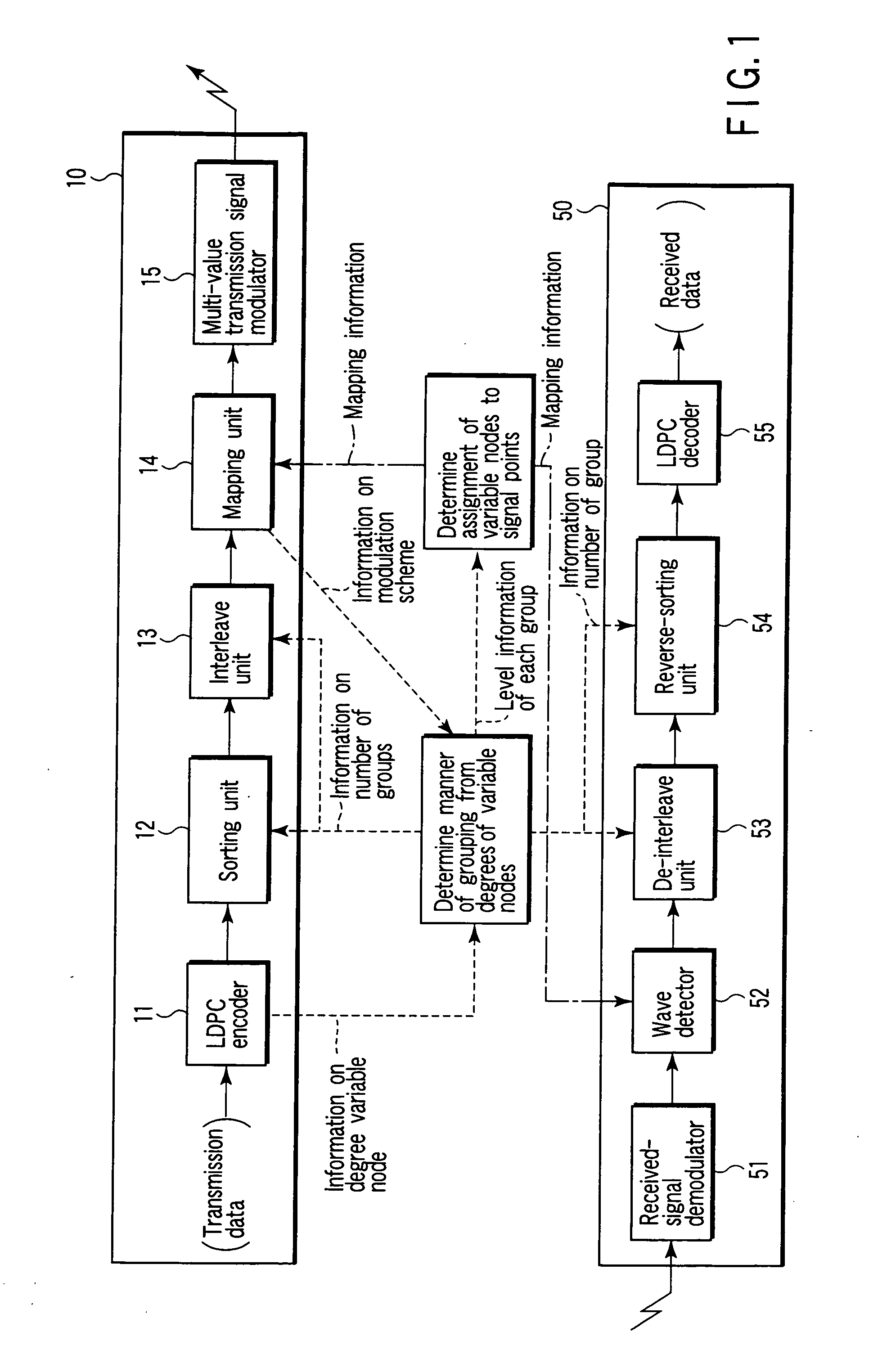
[0045] Referring to FIG. 1, a radio transmitting apparatus and radio receiving apparatus according to the first embodiment will be described. FIG. 1 is a block diagram of these radio transmitting apparatus and radio receiving apparatus.

[0046] The radio transmitting apparatus denoted by reference numeral 10 can appropriately map, to modulation signal points, respective bit sequences encoded by an LDPC encoder to optimize their error resistances. As seen from FIG. 1, the radio transmitting apparatus 10 comprises an LDPC encoder 11, sorting unit 12, interleave unit 13, mapping unit 14 and multi-ary transmission signal modulator 15.

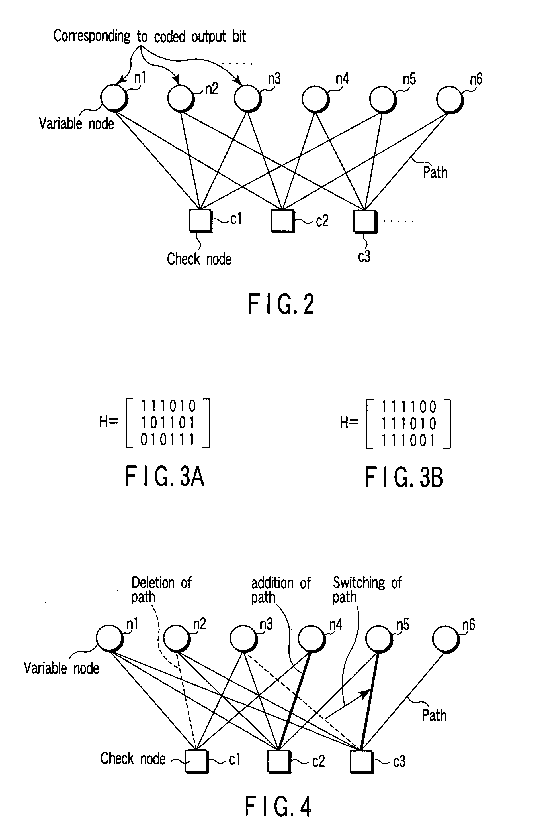
[0047] The LDPC encoder 11 receives transmission data, and performs LDPC coding on it based on a generator matrix G. The generator matrix G is defined as a matrix that satisfies H×G=0 in a predetermined parity check matrix H. LDPC coding is performed to acquire C that satisfies V×G=C where V represents a digital data sequence constituting the transmission d...

second embodiment

[0088] Referring to FIG. 12, a radio transmitting apparatus 20 and radio receiving apparatus 60 according to a second embodiment of the invention will be described. FIG. 12 is a block diagram illustrating configuration examples of the radio transmitting apparatus 20 and radio receiving apparatus 60.

[0089] The radio transmitting apparatus 20 of the second embodiment differs from the radio transmitting apparatus 10 of the first embodiment only in that the former additionally employs a communication channel state receiving unit 21. Further, the radio receiving apparatus 60 of the second embodiment differs from the radio receiving apparatus 50 of the first embodiment only in that the former additionally employs a communication channel state transmitting unit 61. In the first and second embodiments, like reference numerals denote like components, and duplication of explanation will be avoided.

[0090] The communication channel state receiving unit 21 receives, from the radio receiving ap...

third embodiment

[0107] Referring to FIG. 18, a radio transmitting apparatus 10 and radio receiving apparatus 70 according to a third embodiment of the invention will be described. FIG. 18 is a block diagram illustrating configuration examples of the radio transmitting apparatus 10 and radio receiving apparatus 70.

[0108] The radio transmitting apparatus 10 of the third embodiment is similar to the radio transmitting apparatus 10 of the first embodiment. On the other hand, the radio receiving apparatus 70 of the third embodiment differs from the radio receiving apparatus 50 of the first embodiment only in that the former additionally employs a sorting unit 71, interleave unit 72 and weighting unit 73. In the first and third embodiments, like reference numerals denote like components, and duplication of explanation will be avoided.

[0109] In the third embodiment, the radio receiving apparatus 70 repeatedly performs decoding of a received signal.

[0110] The sorting unit 71 and interleave unit 72 have ...


PUM


Abstract

A method for mapping of coded bits using a low density parity check (LDPC) code, comprises encoding information bits by using the LDPC code to generate coded bits, sorting the coded bits in accordance with degrees of variable nodes represented by a parity check matrix of the LDPC code, dividing the sorted coded bits into a plurality of groups in accordance with a using modulation scheme, and mapping the coded bits to respective modulation signal points by considering an error resistance of each of the groups and an error resistance of a corresponding one of the modulation signal points.

Description

CROSS-REFERENCE TO RELATED APPLICATIONS [0001] This application is based upon and claims the benefit of priority from prior Japanese Patent Application No. 2004-088088, filed Mar. 24, 2004, the entire contents of which are incorporated herein by reference. BACKGROUND OF THE INVENTION [0002] 1. Field of the Invention [0003] The present invention relates to the field of digital radio communications, and more particularly to a method for mapping encoded bits using a low density parity check (LDPC) code, which is characterized by digital data error correction and its modulation scheme, also to a transmitting apparatus and receiving apparatus employing this method and program for executing this method. [0004] 2. Description of the Related Art [0005] When using a certain modulation scheme, coded bit sequences assigned to respective modulation signal points generally have different resistances to errors at the modulation signal points in a communication channel. Further, in this case, a pl...

Claims


Application Information

Patent Timeline
Patent Type & Authority Applications(United States)
IPC IPC(8): H03M13/19G06F11/00H03M13/00H03M13/11H03M13/25H03M13/27H04L1/00H04L5/12H04L23/02H04L27/26H04L27/34
CPCH03M13/1102H04L27/3488H03M13/255H03M13/353H03M13/356H03M13/6362H03M13/658H04L1/0057H04L1/0068H04L1/0071H04L5/0007H04L25/4917H04L27/04H04L27/183H04L27/186H04L27/3416H03M13/114
Inventor HARADA, KOHSUKE
Owner KK TOSHIBA
Why Eureka
Try Eureka