
Robotic appliance with on-board joystick sensor and associated methods of operation

a robotic appliance and joystick technology, applied in the direction of vehicle position/course/altitude control, process and machine control, instruments, etc., can solve the problems of inflexible use, large complexity of the device, and high cost of the devi

Inactive Publication Date: 2005-10-06
ROYAL APPLIANCE MFG
View PDF14 Cites 90 Cited by
  • Summary
  • Abstract
  • Description
  • Claims
  • Application Information

AI Technical Summary

Benefits of technology

[0013] In another embodiment, the robotic appliance includes: a housing, a joystick sensor mounted to the housing and configured to provide one or more sensed signals that vary as the robotic appliance traverses a surface area and comes in contact with an obstacle, traction means mounted to the housing, functional means mounted to the housing, a bumper that defines a periphery of the robotic appliance in an x-y plane corresponding to the surface area, wherein the bumper is in operative communication with the joystick sensor so that movement of the bumper in relation to the housing varies the one or more sensed signals provided by the joystick sensor, first control means for powering up the robotic appliance, second control means for selecting an operating mode for the robotic appliance, third control means for starting operation of the robotic appliance, and processing means mounted to the housing and adapted to receive...

Problems solved by technology

Currently, some mobile robotic devices include complex suspension and linkage systems that operate one or more of multiple contact sensors when the outer shell of the device comes in contact with an obstacle.
However, these devices are typically too complex, too expensive, and relatively inflexible for use in multiple types of robotic appliances.

Method used


Image

  • Robotic appliance with on-board joystick sensor and associated methods of operation
  • Robotic appliance with on-board joystick sensor and associated methods of operation
  • Robotic appliance with on-board joystick sensor and associated methods of operation

Examples


Embodiment Construction

[0034] While the invention is described in conjunction with the accompanying drawings, the drawings are for purposes of illustrating exemplary embodiments of the invention and are not to be construed as limiting the invention to such embodiments. It is understood that the invention may take form in various components and arrangement of components and in various steps and arrangement of steps beyond those provided in the drawings and associated description. Within the drawings, like reference numerals denote like elements.

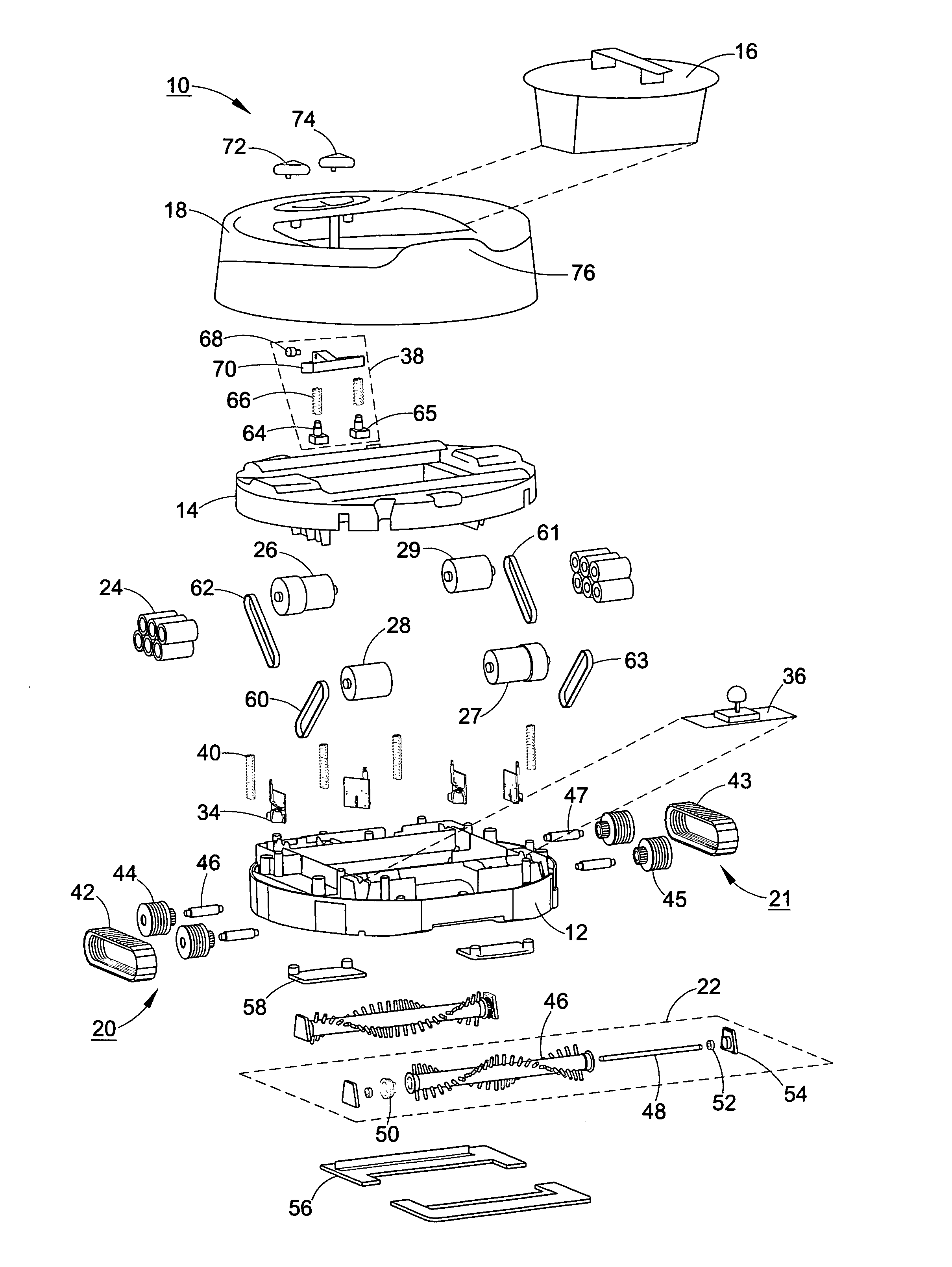
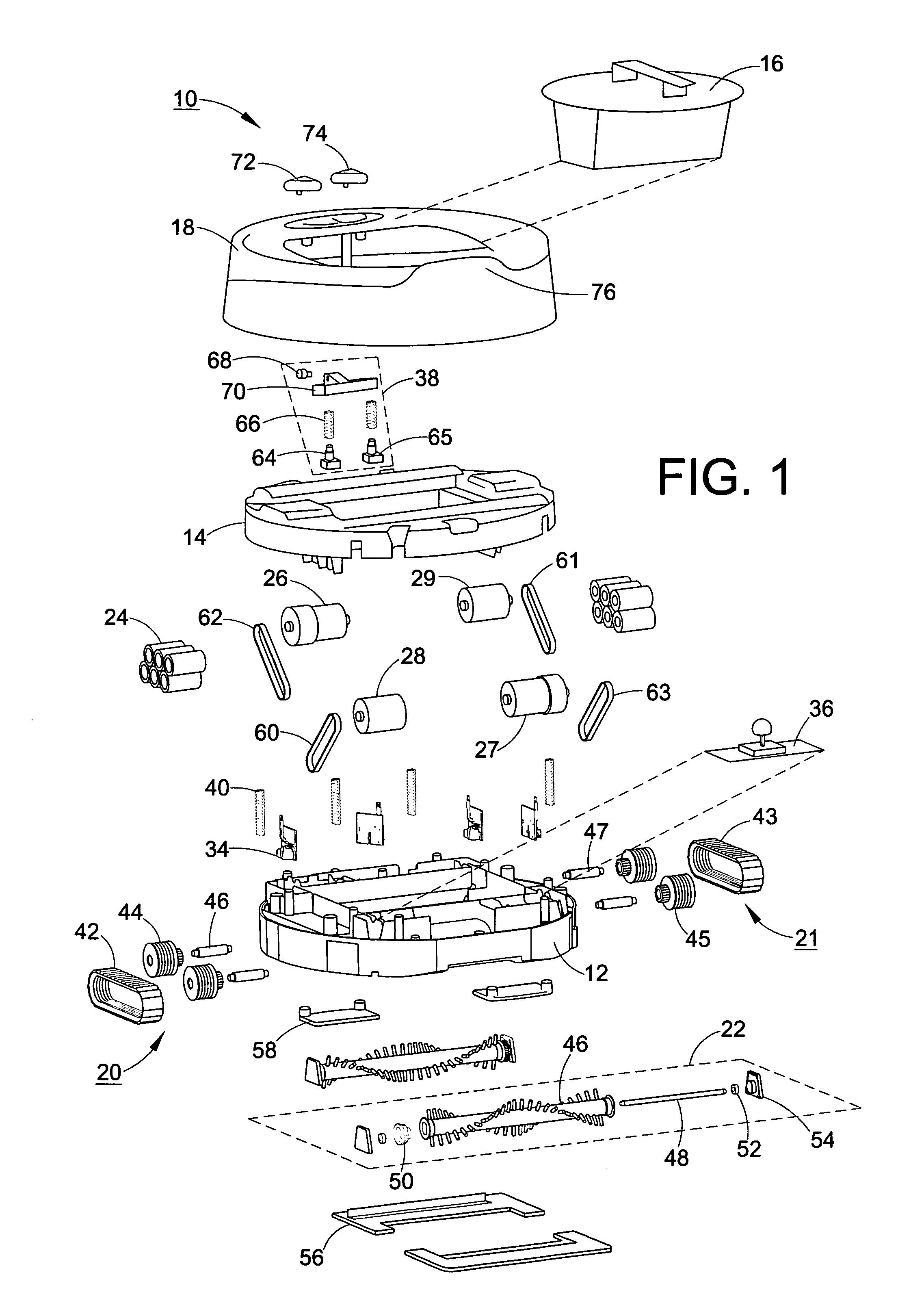
[0035] With reference to FIG. 1, an embodiment of a robotic appliance 10 equipped to function as a robotic sweeper includes a base 12 and a base cover 14 secured to the base 12. A dirt cup assembly 16 is received by the base cover 14 and base 12. A bumper 18 floats above the base cover 14. First and second traction means, which can be first and second drive belt / tread assemblies 20, 21, and first and second cleaning means, which can be first and second brush roll a...


PUM


Abstract

A robotic appliance with a joystick sensor and associated methods of operation are provided. In one robotic appliance includes: a housing, a joystick sensor configured to provide sensed signals that vary as the robotic appliance traverse a surface area and comes in contact with an obstacle, a controller adapted to receive the sensed signals, wherein the controller determines the direction of the obstacle in relation to the robotic appliance and an x-y plane corresponding to the surface area based on the sensed signals and controls the robotic appliance based on the direction of the obstacle, traction means, and a bumper that defines a periphery for a front section and a rear section of the robotic appliance in the x-y plane, wherein the bumper is in operative communication with the joystick sensor so that movement of the bumper in relation to the housing varies the sensed signals.

Description

[0001] This application claims the benefit of U.S. Provisional Patent Application Ser. No. 60 / 559,186, filed on Apr. 2, 2004, the disclosure of which is incorporated herein by reference.BACKGROUND OF INVENTION [0002] The invention relates to a robotic appliance with an on-board joystick sensor. It finds particular application in conjunction with the detection of barriers and other obstacles using the on-board joystick sensor and the corresponding operation of the robotic appliance to perform a functional task while avoiding obstacles and will be described with particular reference thereto. However, it is to be appreciated that the invention is also amenable to other applications. For example, the joystick sensor may be used in conjunction with a wall-following operation of the robotic appliance. [0003] Currently, some mobile robotic devices include complex suspension and linkage systems that operate one or more of multiple contact sensors when the outer shell of the device comes in ...

Claims


Application Information

Patent Timeline
IPC IPC(8): G05D1/02
CPCG05D1/0227
Inventor REINDLE, MARK E.
Owner ROYAL APPLIANCE MFG
Learn More