Method for controlling the material flow during the deep-drawings of sheet metal, and deep-drawing tool

a technology of sheet metal and deep-drawing tools, which is applied in the field of controlling the material flow during the deep-drawing of sheet metal, can solve the problems of relative high height adjustment, relatively complicated solution, and high cost, and achieve the effect of increasing the impedance of sheet metal plate from outside and reducing the amount of breaking elongation

Inactive Publication Date: 2005-10-06
THYSSENKRUPP DRAUZ NOTHELFER GMBH
View PDF5 Cites 14 Cited by
  • Summary
  • Abstract
  • Description
  • Claims
  • Application Information

AI Technical Summary

Benefits of technology

[0011] Pursuant to the inventive method, a Z-shaped blocking step (see feature (a)) is stamped into the sheet metal plate edge at first, i.e. prior to the actual deep-drawing process as the upper and lower sheet metal plate stoppers are closed, wherein the blocking step is then maintained during completion of the base form drawing, thus creating a complete blocking step by the compressed sheet metal plate stoppers and stretching-out the sheet metal plate from inside towards the outside (see feature (b)). Finally, during the further deep-drawing process, the blocking step is reduced in its height, thus facilitating the sheet metal plate trailing from outside (see feature (c)). By way of the inventive 2-shaped blocking step, the sheet metal plate impediment from outside can be increased on the whole and, by the end of the deep-drawing process, it is possible to reduce and even entirely abandon the sheet metal plate impediment by reducing the height of the blocking step through mechanical off-controlling of the deep-drawing step, so that the sheet metal plate trailing takes place exclusively from outside to inside.
[0012] The method being the subject of the present invention may also be applied by reversing the step for the reverse case by performing the deep-drawing process without a blocking step at the beginning, as described according to the other method aspect. This provides the stamping of a blocking step by the aid of the sheet metal holding-down devices only during the deep-drawing process. Hence, the sheet metal plate trailing is impeded by the aid of the blocking step only by the end. This may be of some advantage both for deep-drawing processes with locally substantial deformation, with it being necessary to “serve1” material, and for sheet metal materials having little breaking elongation, e.g. like aluminum.
[0013] The constructive solution provides for a deep-drawing tool as mentioned above. At least one sheet metal stopper, preferably the lower sheet metal stopper along the blocking step is divided into an inner and an outer ring and wherein at least one of these rings is movable relative to the other ring in the direction of holding. The two sheet metal stoppers arranged next to each other may create an adjustable blocking step for the edge of the sheet metal plate and be pressed against a corresponding firm step of the counter-stopper in order to attain the desired sheet metal plate impediment. By actuating the outer ring in a holding direction relative to the inner ring, the step can be reduced from its initial height with maximal blocking effect down to any desired drawing depth, and even down to zero in extreme cases. In conformity with the method according to the other method aspect, this process may also be reversed by initially working virtually without any blocking step between the inner and outer sheet metal stopper and then switching-on the effect of the blocking step by increasing the step between the two rings and raising it up to maximal effect till the end.

Problems solved by technology

A disadvantage according to this method might be involved, if the sheet metal impediment remains constant throughout the deep-drawing process, particularly if the sheet metal is stretched-out beyond the 20% critical expansion in considerably deformed areas and towards the end of the deep-drawing process.
Constructive solutions solely relate to a relatively expensive adjustment in height of deep-drawing rods.
This solution, too, is relatively complicated.

Method used


Image

  • Method for controlling the material flow during the deep-drawings of sheet metal, and deep-drawing tool
  • Method for controlling the material flow during the deep-drawings of sheet metal, and deep-drawing tool
  • Method for controlling the material flow during the deep-drawings of sheet metal, and deep-drawing tool

Examples


Embodiment Construction

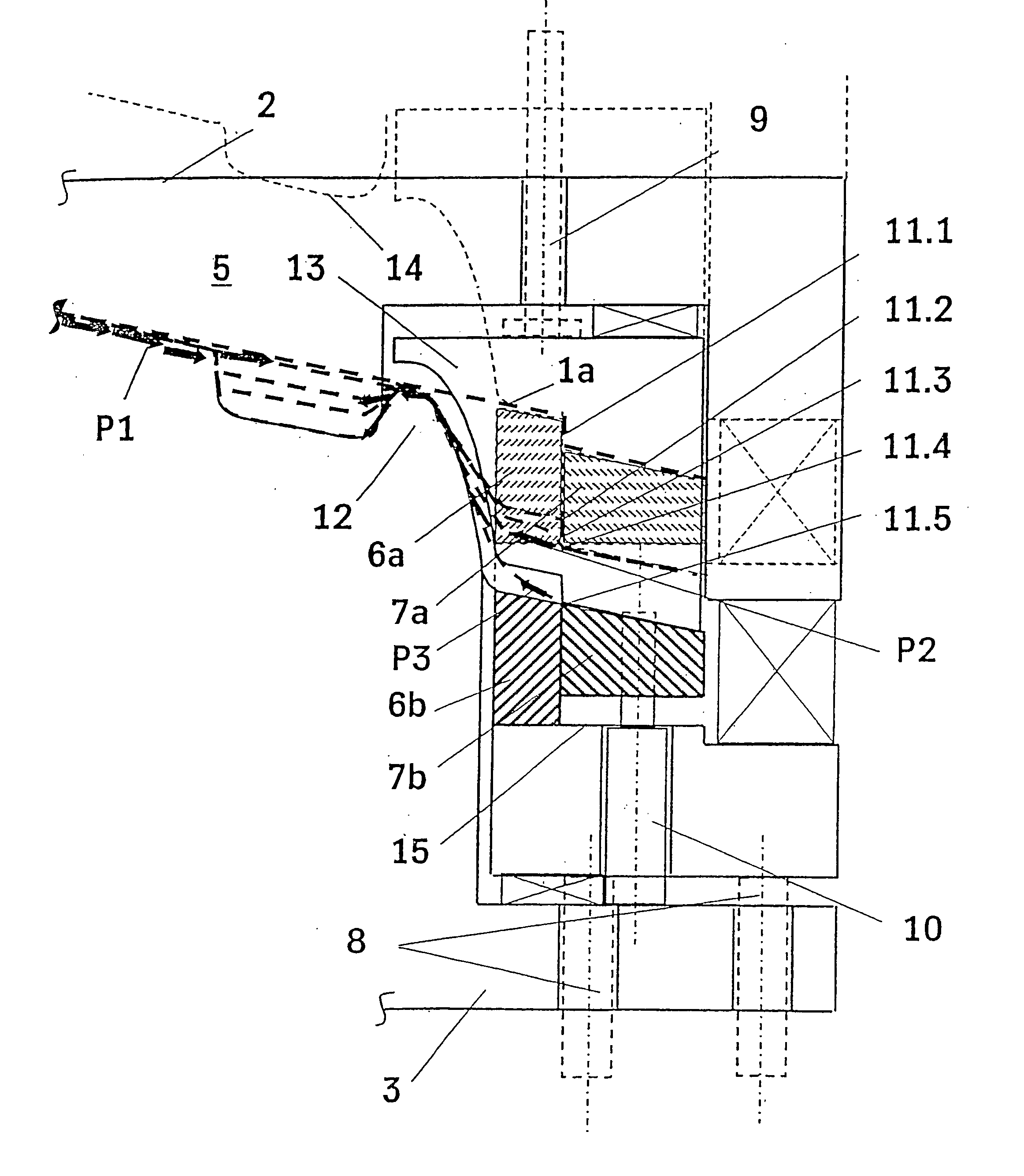
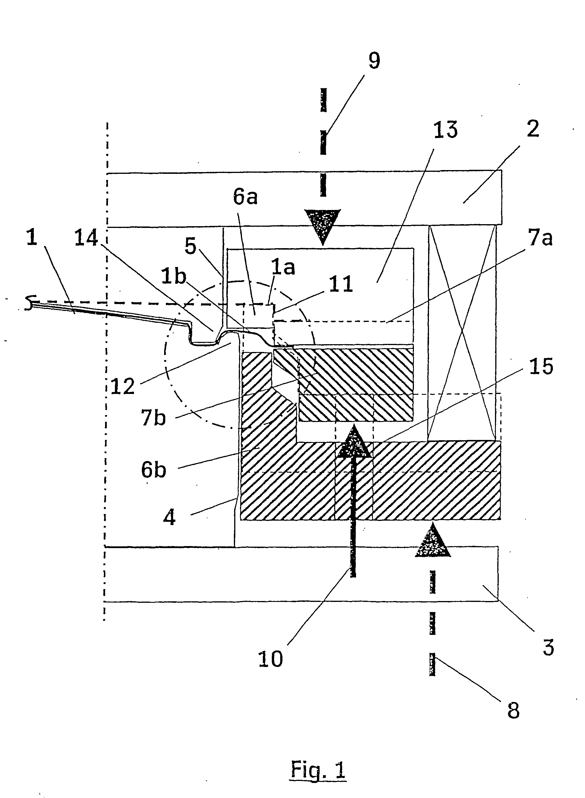
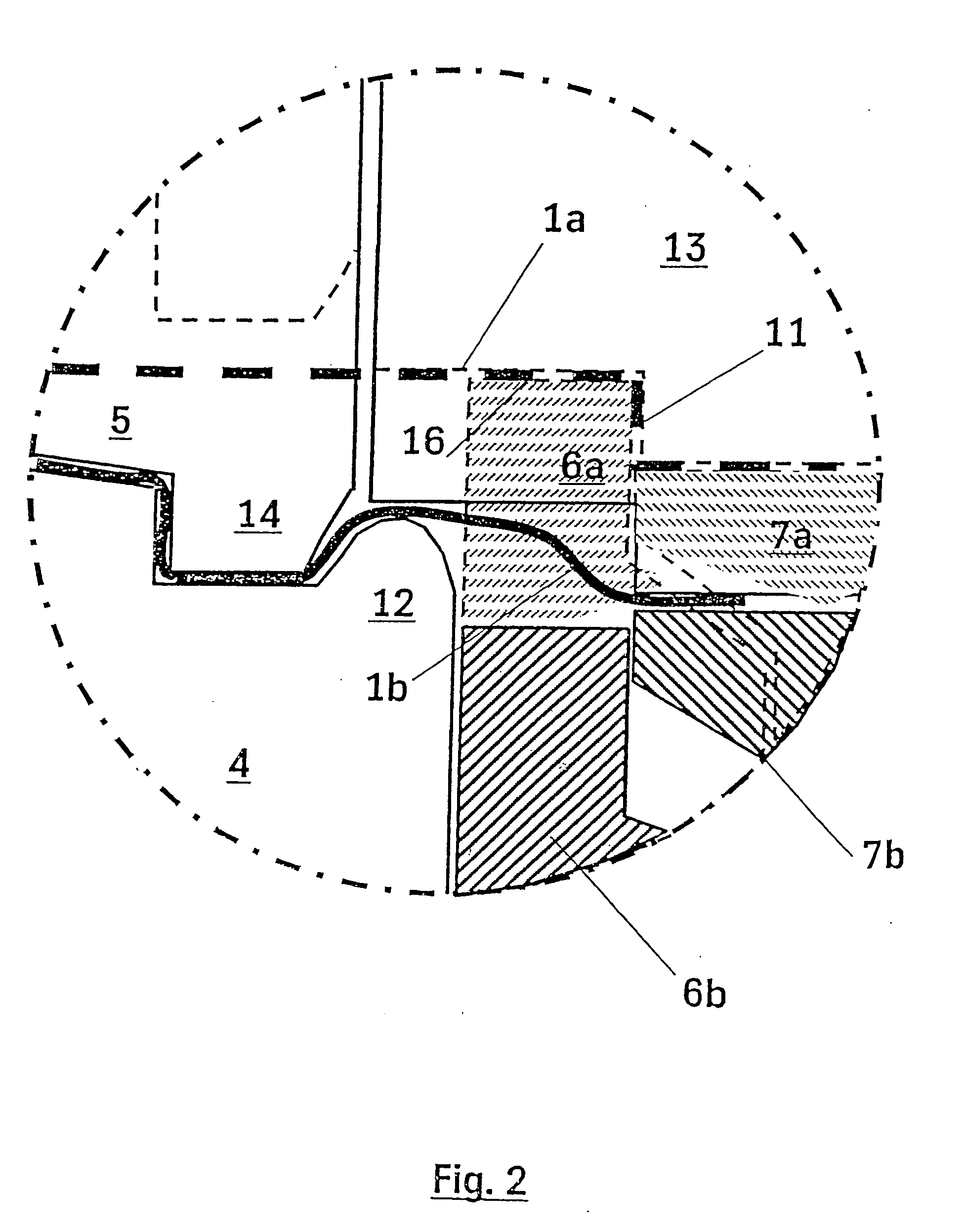
[0019] Referring to the drawings in particular, FIG. 1 shows the sheet metal plate 1 prior to the deep-drawing process with the sheet metal plate edge 1a as a dashed line with blocking step 11. After the deep-drawing process, the sheet metal plate edge 1b is drawn with a continuous line. Sheet metal plate 1 is located between the deep-drawing stamp 4 and matrix 5 that are arranged between top plate 2 and base plate 3 of a conventional press. In a conventional manner, base plate 3 is fixed in stationary arrangement, while top plate 2 is vertically movable for the deep-drawing process. At its underside, the upper sheet metal stopper 13, which is movable relative to a die plate or matrix 5 possesses a step 16 that corresponds to the blocking step 11 of the sheet metal edge 1a. During the deep-drawing process, the upper sheet metal stopper 13 is loaded by spring load 9, also designated as top pneumatic force, and pressed against the sheet metal edge. The two lower sheet metal stoppers 6...


PUM

PropertyMeasurementUnit
heightaaaaaaaaaa
strengthaaaaaaaaaa
step heightaaaaaaaaaa

Abstract

A method for controlling the material flow during the deep-drawing of sheet metal involves compressing the edges of the sheet metal (1) between at least one upper stopper (13) and at least one lower stopper (6, 7) during the deep-drawing process, with a controllable elastic force (8, 9). A corresponding deep-drawing tool is also provided. A Z-shaped blocking step (11) is stamped into the edge (1a) of the sheet metal when the upper and lower stoppers (13, 6, 7) are closed, the basic shape is then produced by deep-drawing, maintaining the blocking step (11) and completely blocking the sheet metal between the stoppers. The sheet metal (1) is outwardly stretched, and the blocking step (11) is then reduced in terms of height, facilitating the outward displacement of the sheet metal towards the outside. The deep-drawing tool has a lower stopper including an inner stopper (6) and an outer stopper (7). The stoppers are arranged in an annular manner on the edge of the sheet metal (1) and can be displaced in relation to each other in the holding direction.

Description

FIELD OF THE INVENTION [0001] The invention relates to a method for controlling the material flow during the deep-drawing of sheet metal, preferably made of high-strength steels and / or multiplephase steels or of aluminum as well as to a deep-drawing tool. BACKGROUND OF THE INVENTION [0002] The use of high-strength steels in car body construction attains ever greater importance within the scope of developing ever lighter motor vehicles. For example, sheet metal plates made of multiple-phase steels are proposed for planking parts. For planking parts made of deep-drawing materials with high hardening values, in particular, it is important that the sheet metal plate is stretched-out over an as “large-surface” as possible. For this purpose, it is state of the art to impede the sheet metal plate trailing from outside by means of a blocking step or blocking bead located on the sheet metal stopper. A disadvantage according to this method might be involved, if the sheet metal impediment rema...

Claims


Application Information

Patent Timeline
Patent Type & Authority Applications(United States)
IPC IPC(8): B21D22/22
CPCB21D22/22
Inventor LOSCH, ALFRED
Owner THYSSENKRUPP DRAUZ NOTHELFER GMBH
Why Eureka
Try Eureka