Driving method of spatial light modulator array, spatial light modulator array, and image forming apparatus

a technology of light modulator array and drive cycle, which is applied in the direction of optics, instruments, static indicating devices, etc., can solve problems such as errors, and achieve the effects of reducing the time of vibration damping, and reducing the time of driving cycl

Inactive Publication Date: 2005-10-06
FUJIFILM HLDG CORP +1
View PDF2 Cites 30 Cited by
  • Summary
  • Abstract
  • Description
  • Claims
  • Application Information

AI Technical Summary

Benefits of technology

[0021] An object of the invention is to provide a driving method of a spatial light modulator array in which writing of an address voltage is enabled without causing an erroneous operation even in a vibration damping time, the spatial light modulator array and an image forming apparatus, and to achieve shortening of a drive cycle.

Problems solved by technology

However, the former is contrary to the demand for a high pixel number, and the latter depends on a clock device development technique.
However, when the writing is performed in the vibration damping time Ts (when the address voltage is inverted), there is a fear that an erroneous operation occurs according to the vibration state. FIG. 32 is an explanatory view showing a case (1) in which a normal operation occurs when the writing is performed in the vibration damping time, and a case (2) in which an erroneous operation occurs.

Method used


Image

  • Driving method of spatial light modulator array, spatial light modulator array, and image forming apparatus
  • Driving method of spatial light modulator array, spatial light modulator array, and image forming apparatus
  • Driving method of spatial light modulator array, spatial light modulator array, and image forming apparatus

Examples


first embodiment

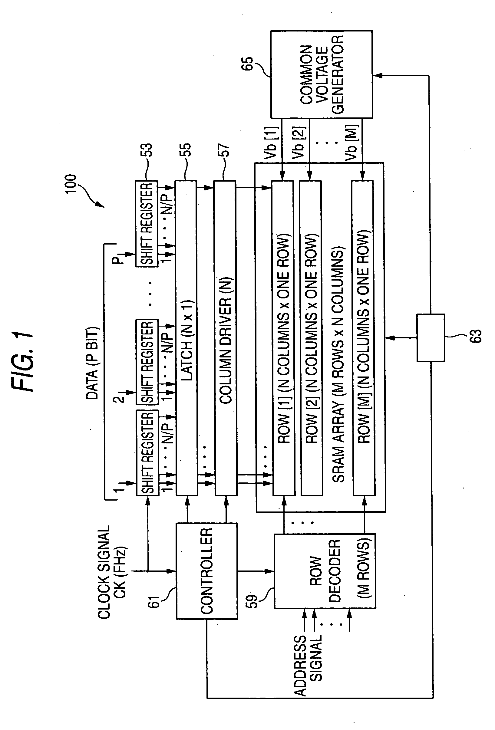
[0099] In a first embodiment, the controller 61 sends a voltage decreasing signal to a control part 63 provided to be attached to the spatial light modulator array 100. The control part 63 having received the voltage decreasing signal decreases the common voltage Vb of each of the spatial light modulators 200 at a specified timing through a common voltage generator 65. The common voltage Vb is supplied to each row in common.

[0100]FIG. 6 is an operation explanatory view showing the behavior of the movable part in the driving method of the invention by correlation of displacement and speed with time.

[0101] In the case where voltage is applied to the movable electrode 3 to drive and displace the micromirror 3, the specified timing is set by the control part 63 before the micromirror 3 reaches the final displacement position. As shown in FIG. 6, the common voltage Vb is decreased before the micromirror is displaced to the final displacement position, so that the speed before the microm...

second embodiment

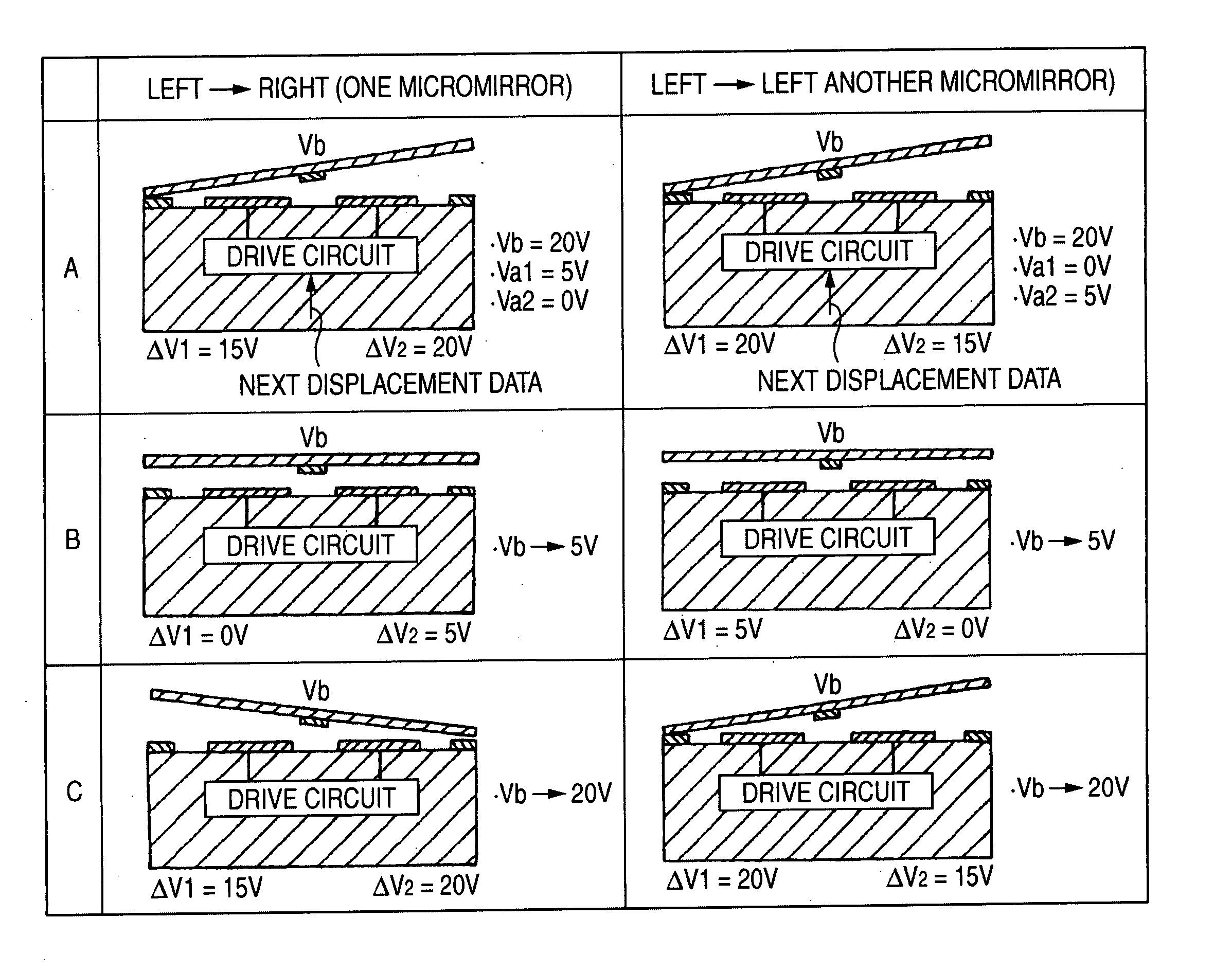
[0109] In the second embodiment, as shown in FIG. 9, there is shows an example in which from a state in which one micromirror 3 and the other micro mirror 3 are in the same contact position (lower contact position in the drawing), the one micromirror 3 transitions to another contact position (upper contact position), and the other micromirror 3 remains in the same contact position (lower contact position).

[0110] In this embodiment, timings when the one micromirror 3 and the other micromirror 3 in the same contact position (lower contact position) transition to next contact states are simultaneously controlled by the common voltage control. The common voltage control is performed in a period of from t0 to t5 in which the micromirror transitions from the first contact position to the next contact position. In the case where the common voltage control is not performed, that is, as shown in FIG. 10, in the case where the common voltage is applied as in the related art, timings Pa and Pb...

third embodiment

[0124] Next, a third embodiment in which phases of plural spatial light modulators 300 are synchronized will be described.

[0125]FIG. 15 is an operation explanatory view showing, by correlation of displacement and common voltage with time, the behaviors of movable parts in the third embodiment.

[0126] In the third embodiment, waveform characteristics of one micromirror 3 and the other micromirror 3 are previously obtained by the measurement device shown in FIG. 12, and a timing t7 when phases of both the micromirrors 3 are first synchronized is obtained in advance. The common voltage control is performed at the timing t7.

[0127] In this embodiment, differently from the above respective embodiments, a possibility that phase synchronization is performed after the contact of the micromirrors 3 becomes high. However, even in the case, the vibration attenuation effect by the above operation can be obtained, and as a result, the vibration disappears after the common voltage control as indi...


PUM

PropertyMeasurementUnit
sizeaaaaaaaaaa
sizeaaaaaaaaaa
voltage Vbaaaaaaaaaa

Abstract

A driving method of a spatial light modulator array having plural spatial light modulators of micro-electro-mechanical system, the plural spatial light modulators each including: a movable part supported to be capable of being elastically displaced and provided with a movable electrode; and a fixed electrode disposed to face the movable part, wherein in a case where the voltages are applied to the electrodes and the movable part is driven and displaced in a fixed electrode direction, an absolute value of an inter-electrode voltage between the movable electrode and the fixed electrode is decreased while the movable part is transitioning in a direction of the fixed electrode.

Description

[0001] This application is based on Japanese Patent application JP 2004-086163, filed Mar. 24, 2004, the entire content of which is hereby incorporated by reference. This claim for priority benefit is being filed concurrently with the filing of this application. BACKGROUND OF THE INVENTION [0002] 1. Technical Field of the Invention [0003] The present invention relates to a driving method of a spatial light modulator array for modulating incident light by displacing a micromirror, to the spatial light modulator array and to an image forming apparatus. [0004] 2. Description of the Related Art [0005] In recent years, attention is paid to, as one of spatial light modulators (SLM), a digital micromirror device (DMD) in which a micromirror is formed on the basis of micro-mechanics technology and the micromirror is tilted to deflect light. The DMD is used for various purposes in the field of optical information processing, such as a projection display, a video monitor, a graphic monitor, a...

Claims


Application Information

Patent Timeline
Patent Type & Authority Applications(United States)
IPC IPC(8): G02B26/00G02B26/08G02F1/01G09G3/34
CPCG02B26/0841G09G3/346G09G2310/06G09G2300/0857G09G2310/0262G09G2300/0842
Inventor KIMURA, KOICHINAKAMURA, HIROCHIKA
Owner FUJIFILM HLDG CORP
Why Eureka
Try Eureka