LED replacement for fluorescent lighting

a technology of led replacement and fluorescent lighting, which is applied in the direction of lighting and heating apparatus, light source combinations, and power with built-in, can solve the problems of loss of the entire series circuit, and achieve the effect of reducing or eliminating any additional electrical components

Inactive Publication Date: 2005-10-13
SAMSUNG ELECTRONICS CO LTD
View PDF25 Cites 105 Cited by
  • Summary
  • Abstract
  • Description
  • Claims
  • Application Information

AI Technical Summary

Benefits of technology

[0032] The present invention comprises a series of embodiments of a replacement lighting unit for a conventional high voltage fluorescent lighting fixture, with the present lighting device utilizing a number of relatively low voltage light emitting diodes (LEDs) to produce the desired light. The LEDs are disposed linearly within a translucent tube, along the outer surface of a solid translucent rod, or grouped at one or both ends of such a solid rod. The LEDs may be in a series or parallel circuit array, as desired. A series circuit works well, as the reliability of such LED devices is such that it is unlikely that any will break down, which would result in loss of the entire series circuit. Moreover, a series circuit of LEDs allows the LEDs to act as a series of mutual voltage reduction devices for the other LEDs in the series circuit, thus reducing or eliminating any additional electrical componentry which might otherwise be required.
[0034] Both the solid rod and hollow tube embodiments preferably incorporate some form of reflective material disposed about approximately one half of the circumference of the rod or tube, in order to transmit the light laterally from one side of the rod or tube. The reflective material may be formed integrally with the rod or tube at the time of manufacture, e.g., by an extruding or other process. A tinted translucent sleeve may be applied over the rod or tube if so desired, and / or the LEDs may be selected to emit a given color, in order to provide light output in a desired color range. The use of LEDs allows their intensity to be adjusted as desired by means of a conventional rheostat or similar control, unlike conventional fluorescent lights.
[0039] It is an object of the invention to provide improved elements and arrangements thereof for the purposes described which is inexpensive, dependable and fully effective in accomplishing its intended purposes.

Problems solved by technology

A series circuit works well, as the reliability of such LED devices is such that it is unlikely that any will break down, which would result in loss of the entire series circuit.

Method used


Image

  • LED replacement for fluorescent lighting
  • LED replacement for fluorescent lighting
  • LED replacement for fluorescent lighting

Examples


first embodiment

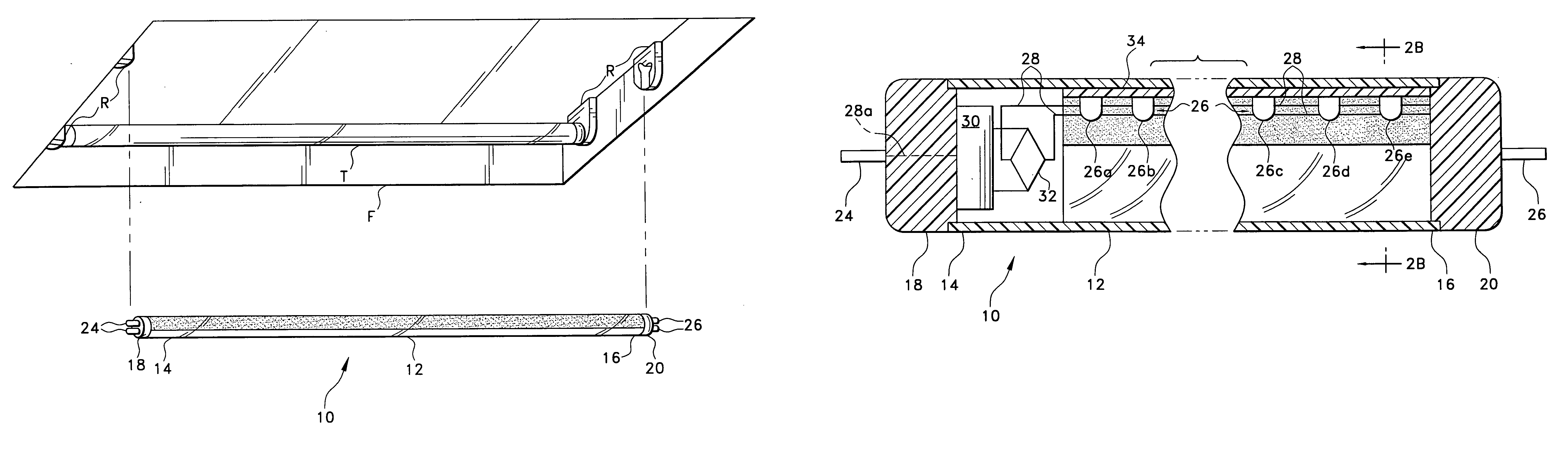
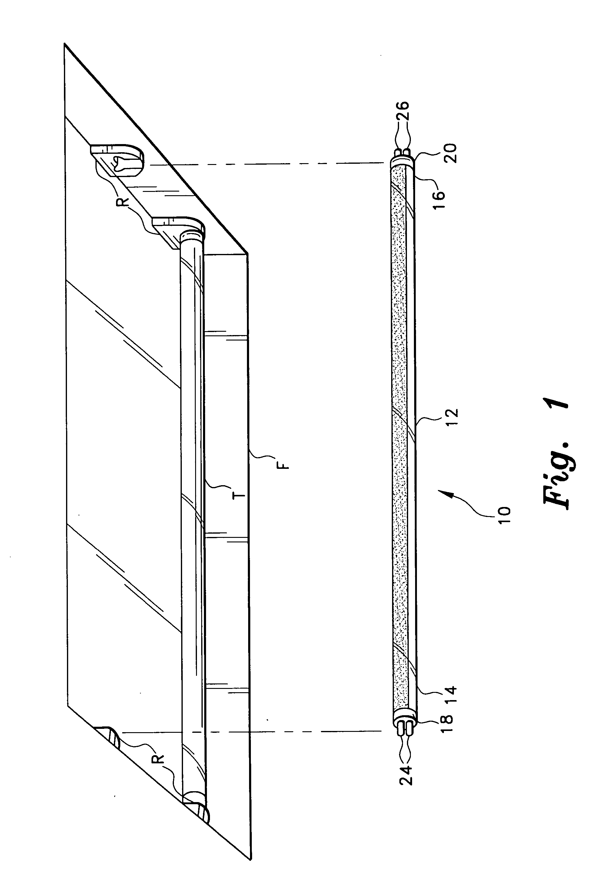
[0051] The present invention comprises various embodiments of a lighting element adapted for installation in a conventional fluorescent lighting fixture. The present lighting element contains one or more (preferably a plurality of) light emitting diodes (LEDs) therein, which provide the light emission from the device. FIG. 1 of the drawings illustrates the installation of a first embodiment LED replacement lighting device 10, within an existing conventional fluorescent lighting fixture F. The fluorescent lighting fixture F is adapted to receive one or more elongate, tubular fluorescent lighting tubes T therein, with the tubes T being secured between opposed electrical receptacles R. While the fluorescent fixture F illustrated in FIG. 1 comprises an overhead fixture containing two straight, elongate tubes or lighting elements, it will be seen that the present LED replacements for fluorescent lighting are adaptable to virtually any configuration of fluorescent lighting element, e.g., ...

second embodiment

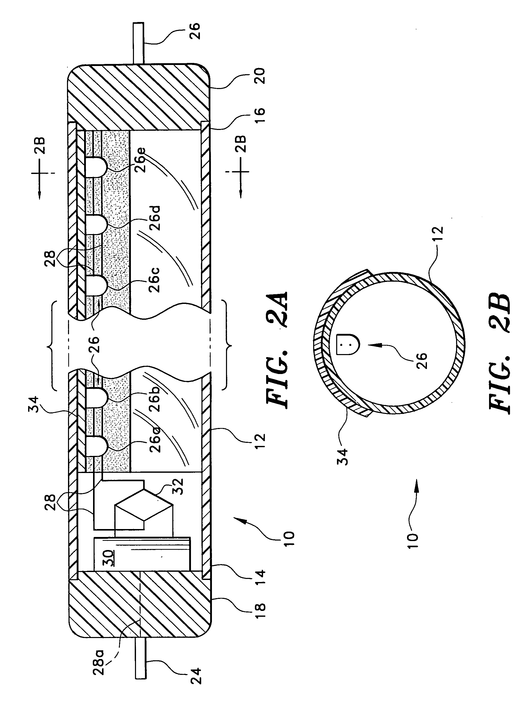
[0061]FIGS. 3A and 3B illustrate the present invention, comprising lighting device 50. The elongate element of the light 50 is formed as a solid, rigid, transparent or translucent rod 52 of suitable material (plastic, glass, etc.), having opposite first and second ends, respectively 54 and 56. Each end is equipped with an end cap, respectively 58 and 60, with corresponding fluorescent fixture receptacle connector pins, respectively 62 and 64, extending from each end cap 58 and 60. Excepting the fact that the elongate element comprises a solid rod 52 rather than a hollow tube, as in the embodiment of FIGS. 2A and 2B, the basic configuration of the lighting element 50 is much like that of the lighting element 10 of FIGS. 2A and 2B, being adapted for installation in a conventional fluorescent lighting fixture.

[0062] A series of white or colored light emitting diodes 66, comprising LEDs 66a, 66b, 66c, etc., is provided for the lighting device 50. However, the LEDs 66 are installed in a ...

embodiment 50

[0063] As in the light 10 of FIGS. 2A and 2B, the light 50 may also include some form of reflective coating 72 (reflective paint, tape, sheathing, etc.) applied along a portion of the circumference of the rod 50, and extending over the LEDs within their receptacle or receptacles 68. In addition, some form of light diffusing means is desirable in the solid rod embodiment 50 of the present invention, and may comprise a series of V-shaped or other shaped notches 74 (shown to the right side in FIG. 3A, or a relatively fine grating 76 (to the left, in FIG. 3A), or other irregularities disposed over the surface of the LED receptacle(s) 68, so long as the means provided is sufficient to diffuse the light as desired.

[0064]FIG. 4 illustrates one end of another alternative embodiment lighting device of the present invention. The light 100 of FIG. 4 comprises a rigid, solid, transparent or translucent rod 102, similar to the rod 52 of FIGS. 3A and 3B. While only a first end 104 of the lighting...


PUM


Abstract

The present invention provides several embodiments of an elongate hollow tubular or solid rod lighting device including a plurality of LEDs therewith and appropriate electrical componentry, and serving as a direct replacement for a conventional fluorescent light tube in a conventional fluorescent lighting fixture. The present lighting device includes appropriate connector pins extending from each end thereof, enabling the device to be installed in a conventional fluorescent lighting fixture with no modification to the fixture. The light may include appropriate electrical componentry such as a step-down transformer to provide the required voltage for the LEDs, either integrally within the light, incorporated in an end cap thereof, or installed separately therefrom in the fixture, as desired. The light may be colored or tinted as desired by the use of LEDs providing the desired color output, and / or by installing a tinted sleeve over the tube or rod as desired.

Description

BACKGROUND OF THE INVENTION [0001] 1. Field of the Invention [0002] The present invention relates generally to electrical lighting devices and systems, and more particularly to a lighting device comprising a series of light emitting diodes (LEDs) incorporated within a clear or translucent tube or rod configured for installation in a conventional fluorescent light fixture. The present LED replacement light includes suitable light directing and / or diffusing means and compatible connector pins and electrical componentry as required for installation and operation in an existing fluorescent light circuit. Alternatively, the replacement may utilize conventional 110-115 volt alternating current or backup battery power as the electrical power source. [0003] 2. Description of the Related Art [0004] A number of different principles of electrical lighting have been developed over the years. Incandescent lighting was the first lighting principle to receive widespread use, and is still the most ...

Claims


Application Information

Patent Timeline
Patent Type & Authority Applications(United States)
IPC IPC(8): F21K99/00H05B44/00
CPCF21K9/17F21S9/022F21V7/005F21V17/04F21V23/02F21V25/12Y02B20/386H05B33/0803H05B33/0809H05B33/0815F21Y2103/003Y10S362/80F21Y2101/02F21K9/27F21Y2103/10F21Y2115/10F21Y2113/00F21K9/68Y02B20/30H05B45/382H05B45/3578F21V5/043
Inventor ROBERTSON, JONAS J.CURRIE, ROBERT M.
Owner SAMSUNG ELECTRONICS CO LTD
Why Eureka
Try Eureka