USB upstream device, USB connector, and USB cable

Inactive Publication Date: 2005-10-13
FUJITSU LTD
View PDF7 Cites 22 Cited by
  • Summary
  • Abstract
  • Description
  • Claims
  • Application Information

AI Technical Summary

Benefits of technology

[0029] As a result, same as in the case of the one aspect, the parasitic capacitance of the second signal line is prevented from being charged by leak current or the like, and the potential of the second signal line is prevented from elevating, and when connected to the USB, the transfer capacity of the USB upstream device is not falsely judged. If separated from the USB in the midst of data transfer, since the second signal line is pulled down immediately after being separated, the first and second signal lines are recognized as idle state, and the USB upstream device is normally transferred to the suspend state.
[0030] In addition, also during a fi

Problems solved by technology

A first problem is false recognition

Method used


Image

  • USB upstream device, USB connector, and USB cable
  • USB upstream device, USB connector, and USB cable
  • USB upstream device, USB connector, and USB cable

Examples


first embodiment

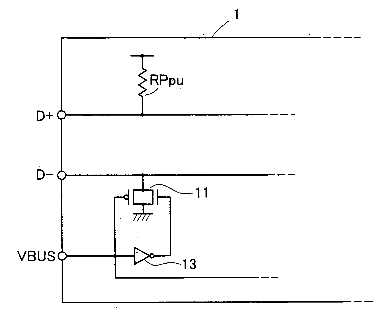
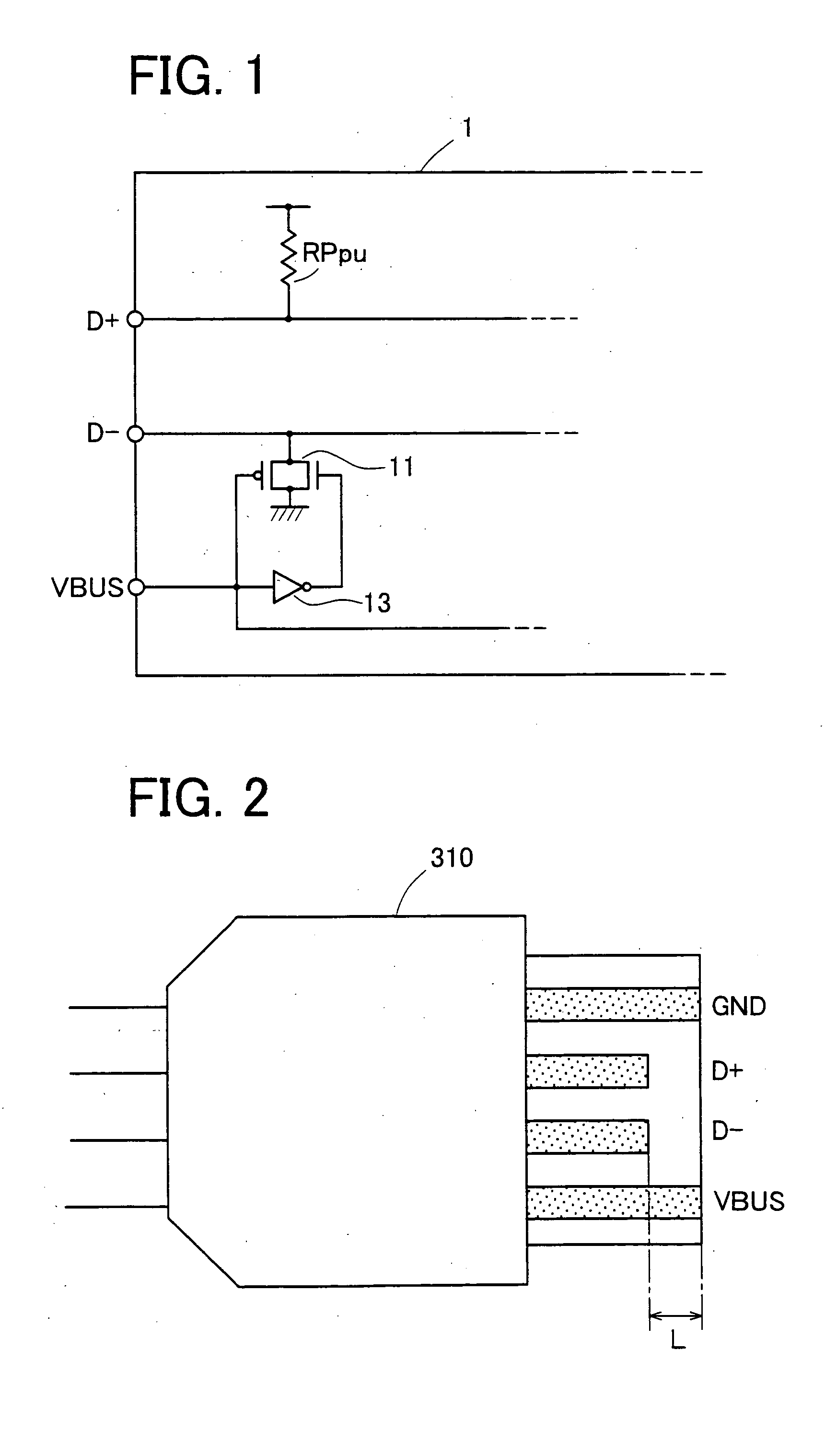
[0048]FIG. 1 is a circuit diagram of a USB upstream device in the invention. The USB upstream device 1 has a pull-up resistance RPpu connected between a signal line D+ and supply voltage, and a switch circuit 11 between a signal line D− and grounding voltage. The switch circuit 11 may be, for example, a so-called transfer gate, composed by mutually connecting a source terminal and a drain terminal of a PMOS transistor and a NMOS transistor. A VBUS line is connected to a gate terminal of a PMOS transistor, and an inverted signal inverted from the VBUS line through an inverter gate 13 is connected to a gate terminal of the NMOS transistor.

[0049] When the USB upstream device 1 is connected to the USB, power is supplied through VBUS line in the USB cable. This is the power to be supplied to a self-supporting device not having power supply wire such as mouse. In the USB upstream device 1, supply voltage supplied to the VBUS line is supplied to the gate terminal of the PMOS transistor as ...

fourth embodiment

[0071] The USB upstream device 4 in the fourth embodiment shown in FIG. 5 is an embodiment applied to the device conforming to USB 2.0 standard. In the USB 2.0, one device supports two transmission modes, a high speed mode and a full speed mode. In the full speed mode, the signal line D+ is pulled up, and in the high speed mode, the signal lines D+ and D− both operate in the high impedance state.

[0072] In the USB upstream device 4, a pull-up resistance element RPpu is provided between the signal line D+ and supply voltage through switch circuit 45, and resistance element 43 is provided between the signal line D− and grounding voltage through switch circuit 41.

[0073] Switch circuits 41, 45 are same in configuration as the switch circuit 11 (FIG. 1) in the first embodiment. In the USB upstream device 4, a control signal FS_OP instructing a transmission mode controls the gate terminal of NMOS transistors for composing the switch circuits 41, 45, and its inverted signal, / FS_OP signal ...


PUM


Abstract

It is an object to provide a USB upstream device, a USB connector, and a USB cable, capable of operating stably by preventing malfunction due to a signal line defined as a high impedance state depending on a data transmission mode in the USB upstream device, when inserting or removing the USB upstream device into or from the USB. In a USP upstream device 1, a switch circuit 11 is provided between a signal line D− and grounding voltage. When the USB upstream device 1 is connected to the USB, power is supplied through VBUS line in the USB cable and the signal line D− is cut off from the grounding voltage. When cut off from the USB, the power supply through the VBUS line is cut off, and the switch circuit 11 conducts. Then, a discharge route is established. Unnecessary charge such as leak current or the like is discharged to the grounding voltage through the switch circuit 11. As a result, in a state separated from the USB, a voltage level of the signal line D− is maintained at a low voltage level.

Description

CROSS-REFERENCE TO RELATED APPLICATIONS [0001] This application is a continuation application based upon and claims the benefit of the prior PCT International Patent Application No. PCT / JP2003 / 005247 filed on Apr. 23, 2003, the entire contents of which are incorporated herein by reference.BACKGROUND OF THE INVENTION [0002] 1. Field of the Invention [0003] The present invention relates to a USB upstream device, a USB connector, and a USB cable, and more particularly to a USB upstream device, a USB connector, and a USB cable capable of operating stably even when inserting or removing the USB upstream device into and from the USB or in noisy environment. [0004] 2. Description of the Related Art [0005] In a universal serial bus (USB) disclosed in non-patent document 1 described below, a USB peripheral device (USB upstream device) can be inserted or removed into or from the USB while power is being supplied. Depending on a terminal end state of signal lines D+, D− in the USB upstream dev...

Claims


Application Information

Patent Timeline
IPC IPC(8): G06F3/00G06F13/00G06F13/40
CPCG06F13/4077G06F2213/0042G06F13/4081
Inventor TSUTSUI, TATSUMI
Owner FUJITSU LTD
Why Eureka
Try Eureka