Liquid-crystal display, projector system, portable terminal unit, and method of driving liquid-crystal display

a technology of liquid crystal display and projector system, which is applied in the direction of cathode-ray tube indicators, static indicating devices, instruments, etc., can solve the problems of streak-like irregularities along data lines, deteriorating display image quality, and errors in all data lines potentials, so as to eliminate streak-like irregularities

Inactive Publication Date: 2007-05-10
NEC CORP
View PDF8 Cites 21 Cited by
  • Summary
  • Abstract
  • Description
  • Claims
  • Application Information

AI Technical Summary

Benefits of technology

[0031] In the case of the present invention, it is possible that by differentiating a sequence for outputting a control signal to n control lines belonging to each group in a horizontal period for predetermined period, a sequence for outputting video signals to data lines belonging to each group in a horizontal period is differentiated for predetermined period, a data line in which potential is fluctuated is fluctuated for predetermined period, and only the potential of a data line set to a specific position in each group is prevented from being fluctuated. Thereby, when viewing the whole image, it is possible to eliminate streak-like irregularity.

Problems solved by technology

However, the above prior art has the following problem.
It is clarified that a liquid-crystal display for performing the above block division driving and a liquid-crystal display according to COG connection have a problem that a display image quality is deteriorated.
Speaking strictly, an error occurs in potentials of all data lines.
Because the error voltage causes a luminance difference between pixels and the luminance difference influences all pixels on the same data line, streak-like irregularity along a data line is generated.
However, it is difficult to completely eliminate parasitic capacitances.
Moreover, also in the case of a liquid-crystal display according to COG connection, a problem occurs that a pixel column connected to one of a plurality of data lines connected to one output terminal of a data line driving IC is different from other pixel column in luminance and the luminance appears as streak-like irregularity.
However, a parasitic capacitance between adjacent data lines most influences the potential of a certain data line.
However, a liquid-crystal display according to COG connection is used for a direct-sight for a small portable terminal provided with color filters of R, G, and B. Particularly, when the color filters are arranged like a stripe along data lines and the number of data lines to be driven by one output of a data line driving IC is 3, even if voltage fluctuation occurs due to parasitic capacitances of the data lines, it is difficult to recognize the voltage fluctuation as streak-like irregularity because a luminance change is equal between data line of the same color and therefore, it has not been recognized as a problem.
However, when setting the number of time divisions to 3 or more (for example, multiple of 3) and using a three-plate-type projector without adding a color filter, this becomes a large problem similarly to the case of a liquid-crystal display for performing block division driving.

Method used


Image

  • Liquid-crystal display, projector system, portable terminal unit, and method of driving liquid-crystal display
  • Liquid-crystal display, projector system, portable terminal unit, and method of driving liquid-crystal display
  • Liquid-crystal display, projector system, portable terminal unit, and method of driving liquid-crystal display

Examples


first embodiment

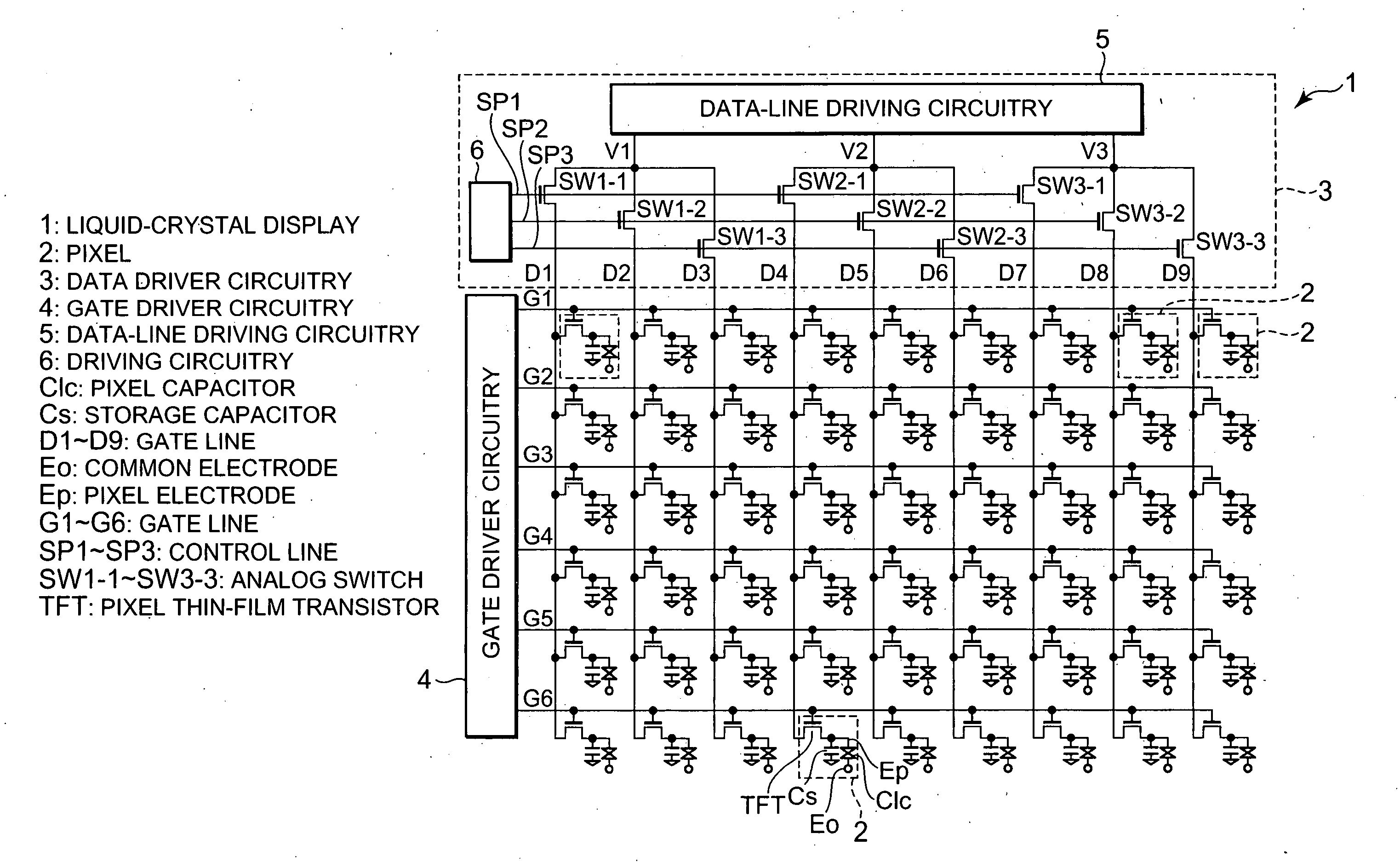
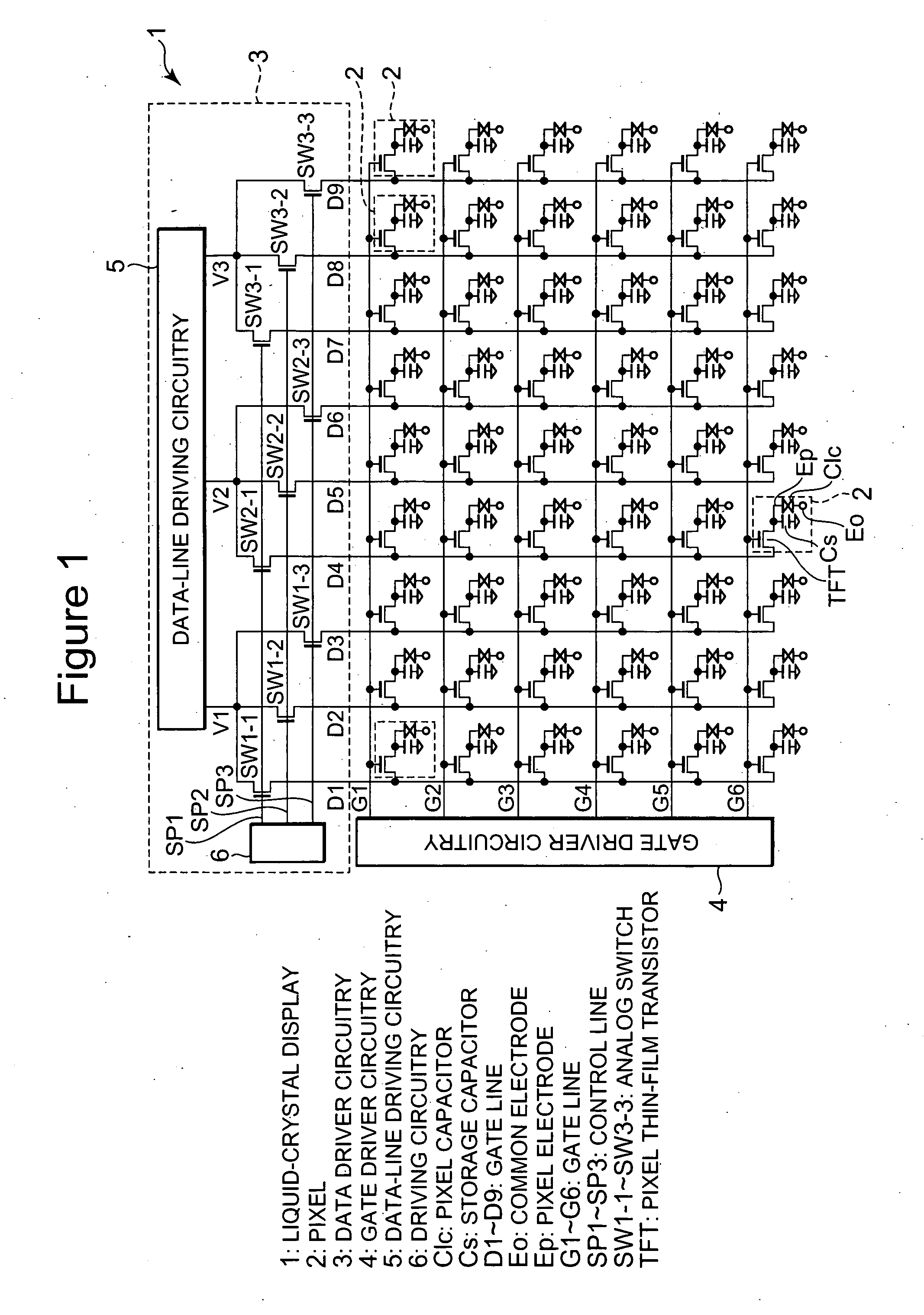
[0070] Embodiments of the present invention are specifically described below by referring to the accompanying drawings. First, first embodiment of the present invention is described. FIG. 1 is a block diagram showing the liquid-crystal display of this embodiment. As shown in FIG. 1, in the liquid-crystal display 1, a TFT-side glass substrate (not illustrated) and an opposite-side glass substrate (not illustrated) are set in parallel with each other and a liquid-crystal layer (not illustrated) is formed between the both substrates.

[0071] Moreover, data lines D1 to D9 (also generally referred to as data lines D) extending in the row direction are set on the TFT-side glass substrate and gate lines G1 to G6 (also generally referred to as data lines G) extending in the column direction are set on the same TFT-side glass substrate. Furthermore, a pixel 2 is formed at each of proximity points between the data lines D1 to D9 and the gate lines G1 to G6. That is, in the case of this liquid-c...

second embodiment

[0099] Then, advantages of this embodiment are described below. In the case of this embodiment, it is possible to further shorten a cycle for changing a writing sequence in a data line compared with the above described first and Thereby, it is possible to make it more difficult that streak-like irregularity is recognized. As a result, it is possible to almost completely prevent streak-like irregularity from being recognized.

[0100] Moreover, by equalizing the number of times for displaying the same video signal in one vertical period of an external signal with the number of data lines to be connected to one output terminal of data driving circuitry, that is, the number of data lines belonging to one group, it is possible to almost equalize potential fluctuations generated in all data lines in one vertical period of a video signal input to the signal processing circuitry 7 from a signal source. Therefore, it is possible to make it more difficult that the luminance difference between ...

sixth embodiment

[0137] Then, sixth embodiment of the present invention is described below. Because a configuration of the liquid-crystal display of this embodiment is the same as the configuration of the liquid-crystal display of the fourth embodiment, its description is omitted. Operations of the liquid-crystal display of this embodiment are described below. This embodiment is obtained by further improving the driving method of the liquid-crystal display of the fifth embodiment. In the case of the driving method of the liquid-crystal display of this embodiment, an operation in a certain vertical period is the same as the operation shown in FIG. 18. Moreover, FIGS. 19 and 20 are timing charts respectively showing operations of data driver circuitry of the liquid-crystal display of this embodiment by assigning time to the axis of abscissa and potential of each wiring to the axis of ordinate, in which FIG. 19 shows the operation in a vertical period next to the vertical period shown in FIG. 18 and FI...


PUM


Abstract

A sequence for applying pulses to control lines in a horizontal period is differentiated for every horizontal period or vertical period and a sequence for data driver circuitry to write signals in data lines in a horizontal period is differentiated for every horizontal period or vertical period so that potential fluctuations of data lines generated at the time of sampling are temporally made uniform so as to make recognition of streak-like irregularity difficult.

Description

BACKGROUND OF THE INVENTION [0001] 1. Field of the Invention [0002] The present invention relates to a liquid-crystal display for time-division-writing video signals for one pixel row and driving method, a projector system on which the liquid-crystal display is mounted, and a portable terminal unit. [0003] 2. Description of Related Art [0004] A liquid-crystal projector provided with three liquid-crystal displays corresponding to three primary colors of red (R), green (G), and blue (B) can display a video of a high-luminance, high-definition, and large-screen video. Therefore, the liquid-crystal display is the mainstream of projectors. [0005] A liquid-crystal display used for this liquid-crystal projector normally uses a monochromatic liquid-crystal display in which the diagonal of a display screen is 2″ or less in order to decrease the projector in size and cost. Particularly, because a liquid-crystal display using a P—Si (polysilicon)-TFT (Thin film transistor) has a high mobility ...

Claims


Application Information

Patent Timeline
Patent Type & Authority Applications(United States)
IPC IPC(8): G09G3/36
CPCG09G3/002G09G3/2018G09G3/3688G09G5/399G09G2310/0235G09G2310/027G09G2310/0297
Inventor SEKINE, HIROYUKIOKUMURA, FUJIO
Owner NEC CORP
Why Eureka
Try Eureka