Miniature sensor

Inactive Publication Date: 2005-10-20
ANALATOM
View PDF15 Cites 63 Cited by
  • Summary
  • Abstract
  • Description
  • Claims
  • Application Information

AI Technical Summary

Problems solved by technology

Such micro-sensors are not without drawbacks, however.
For example, they are often fragile and difficult to handle.
In addition, micro-sensors often are limited in their functionality.
For example, low-dimensional strain sensor assemblies often lack the capability to det

Method used


Image

  • Miniature sensor
  • Miniature sensor
  • Miniature sensor

Examples


Embodiment Construction

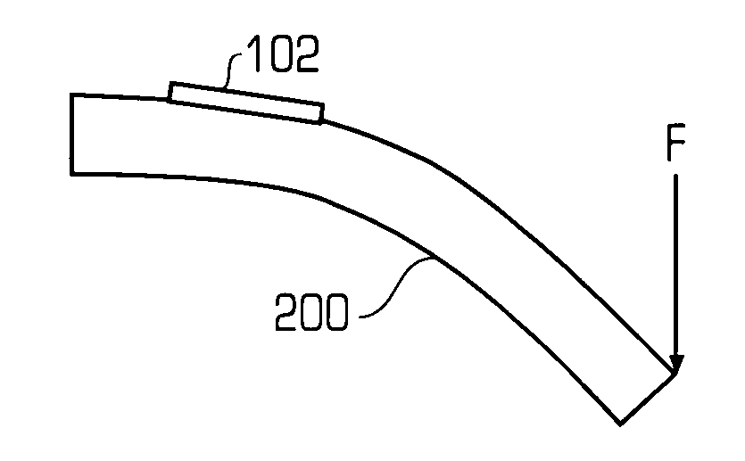
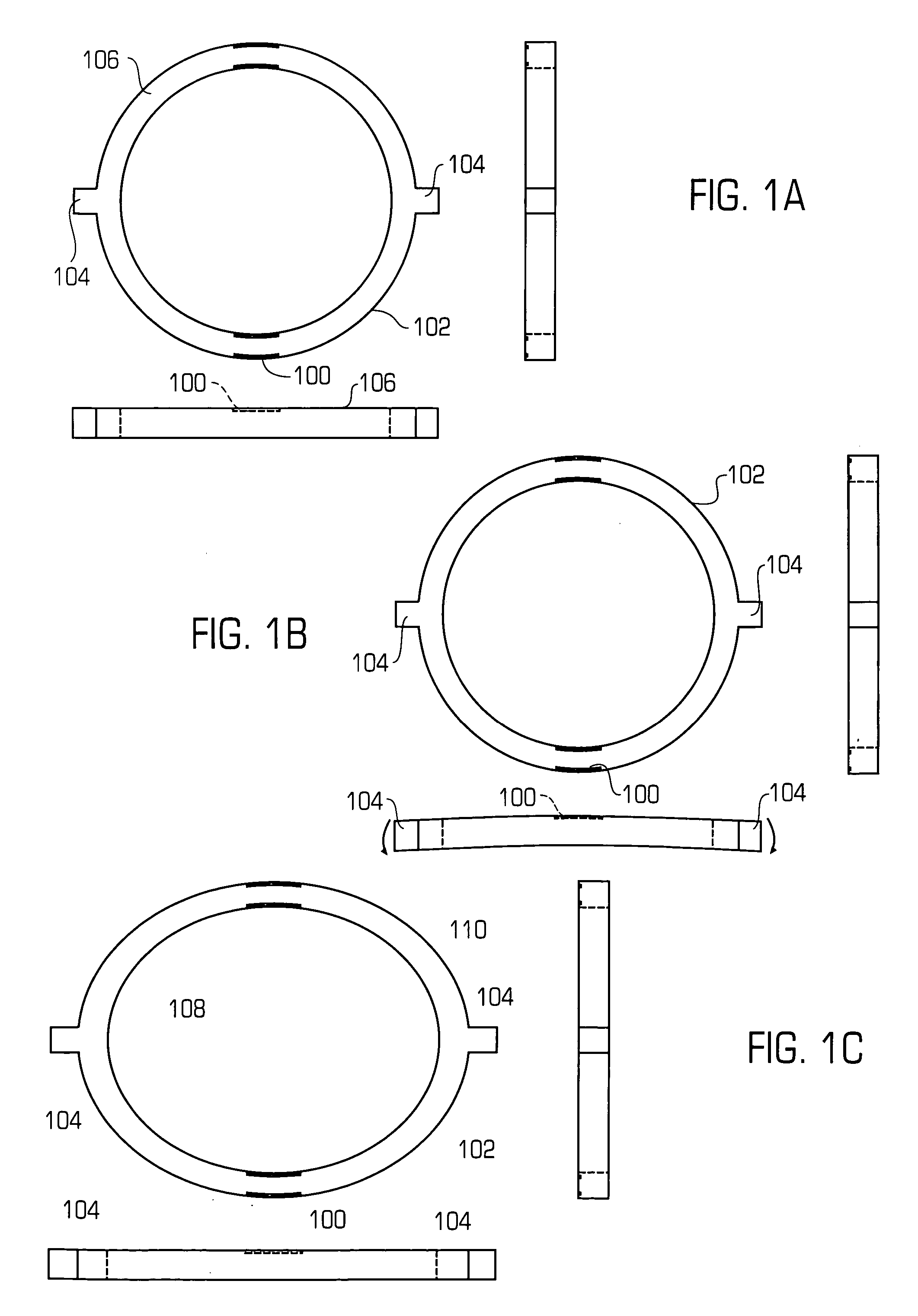
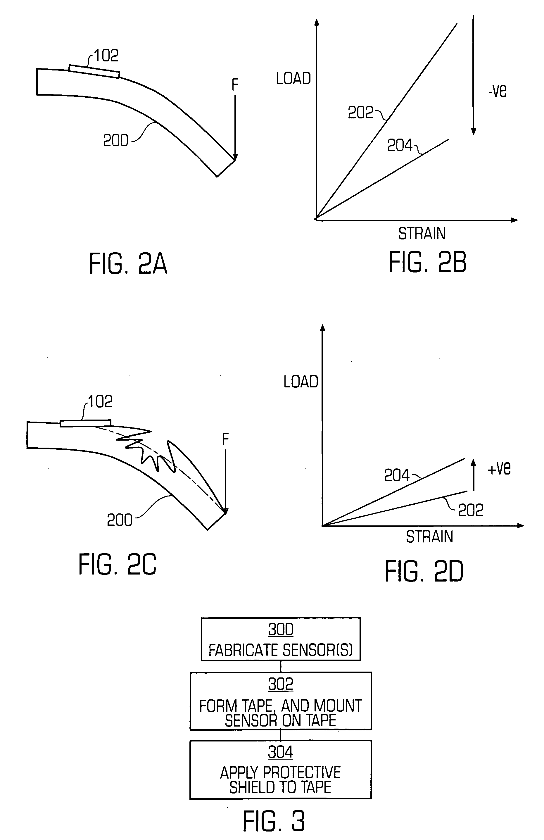
[0020] In one sense, the invention relates to a low-dimensional strain sensor that can detect multiple modes of deformation. The configuration and operation of this strain sensor is shown conceptually in FIGS. 1A-1C. Here, MEMS techniques are employed to fabricate a number of piezoresistors 100 directly into a toroidal, or generally ring-shaped, substrate 102. By employing MEMS techniques, the toroidal substrate 102 can be made small and flat, yielding a compact and lightweight sensor.

[0021] In addition, the use of MEMS fabrication techniques allows for the fabrication of low-profile substrates 102 that have piezoresistors 100 that are fabricated directly into or upon the upper surface 106 of the substrate 102 (as can be seen in the side view of FIG. 1A), without protruding upward from the upper surface 106. In this manner, the piezoresistors 100 are located off the substrate's 102 neutral axis of bending, allowing the piezoresistors 100 to differentiate between multiple deformatio...


PUM


Abstract

A strain sensing apparatus including a deformable substrate is presented. The deformable substrate is configured to detect a strain of the body that can be coupled to the deformable substrate. Sometimes, the deformable substrate is a flexible substrate having an upper surface and an opposite lower surface. The lower can be coupled to the body. There are sensing elements fabricated within the flexible substrate and proximate to the upper surface to detect properties of the body. The strain sensing apparatus is able to detect different strain modes, such as whether the strain is the result of bending of a body or a uniaxial elongation. Furthermore, the apparatus is small and less fragile than most conventional sensors, making it easy to use.

Description

[0001] Pursuant to 35 U.S.C. § 119(e), this application claims the benefit of U.S. Provisional Application No. 60 / 540,843, which was filed on Jan. 30, 2004.BRIEF DESCRIPTION OF THE INVENTION [0002] This invention relates to sensors. More specifically, this invention relates to microstructure sensors. BACKGROUND OF THE INVENTION [0003] Efforts in sensor technology have often been directed toward reducing the size of sensors and sensing elements. Smaller sensors are desirable for a number of reasons. For example, smaller sensors are more easily placed within small spaces, and are often lighter and easier to handle. Recent efforts have focused on fabricating sensors according to micromachining and micro-electro-mechanical-systems (MEMS) methods, to create low-profile and / or “low-dimensional” micro-sensors that are fabricated on substrates such as silicon wafers. These MEMS sensors can be made quite small, relative to conventional sensors. [0004] Such sensors can be utilized in a number...

Claims


Application Information

Patent Timeline
IPC IPC(8): G01L1/18G01L1/22G01L11/00G01M5/00
CPCG01L1/18G01L1/2206G01M5/0083G01L1/2262G01M5/0041G01L1/2231
Inventor NIBLOCK, TREVOR GRAHAM EDWARD
Owner ANALATOM
Why Eureka
Try Eureka