Electronic light generating element light bulb

Active Publication Date: 2005-10-27
LIGHTING SCI GROUP
View PDF53 Cites 79 Cited by
  • Summary
  • Abstract
  • Description
  • Claims
  • Application Information

AI Technical Summary

Benefits of technology

[0013] The heating, inefficiency, and color problems of incandescent and fluorescent light bulbs and lack of brightness, objectionable color, and unappealing physical appearance of conventional LED light bulbs are overcome by the principles of the present electronic light generating element light bulb which utilizes a circuit that does not include a transformer, uses a circuit to overdrive electronic light generating elements to produce a higher perceived amount of light, and may include at least three different colors to produce a desired color of white light. In one embodiment, the electronic

Problems solved by technology

While the incandescent light bulb is effective in producing large amounts of light, these light bulbs are very inefficient in that a substantial portion of the energy used to generate the light is immediate converted into heat.
The inefficient use of energy is expensive and the resulting heat is generally undesirable as it can cause an individual handling the lit light bulb to receive a burn injury, especially with higher wattage light bulbs.
Another limitation of a conventional incandescent light bulb is its limited life span.
The life span problem is particularly problematic in applications where the light bulb is not readily accessible, such as in high locations or in complex fixtures, and requires manual labor and/or machine support for changing the light bulb.
For example, changing traffic light bulbs, particularly those suspended from wires or located at a higher elevation, is a particularly difficult and expensive task as it requires both labor and a specialized vehicle having a lift for raising someone to a height of the traffic light to change the light bulbs.
While the fluorescent light bulb is an improvement of the incandescent light bulb in terms of having a longer life span, the use of the fluorescent light bulb is still commercially limited due to a number of factors, including: objectionable color, efficiency concerns, limited configurations, environmental concerns, and limited life spans.
However, LEDs have certain limiting factors and, thus, have not been commercially viable for general purpose lighting.
Such limitations include narrow illumination beam widths at higher efficiency outputs, ultra-narrow frequency bandwidths, and lower luminance output.
If a current exceeds a maximum specified forward current for a long enough duration of time, as defined by a manufacturer of the LED, a catastrophic failure causing complete or partial damage to the functionality of the LED may result.
While this technique is ef

Method used


Image

  • Electronic light generating element light bulb
  • Electronic light generating element light bulb
  • Electronic light generating element light bulb

Examples


Example

DETAILED DESCRIPTION OF THE DRAWINGS

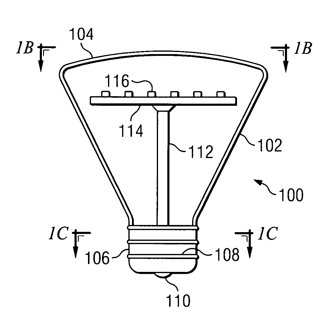
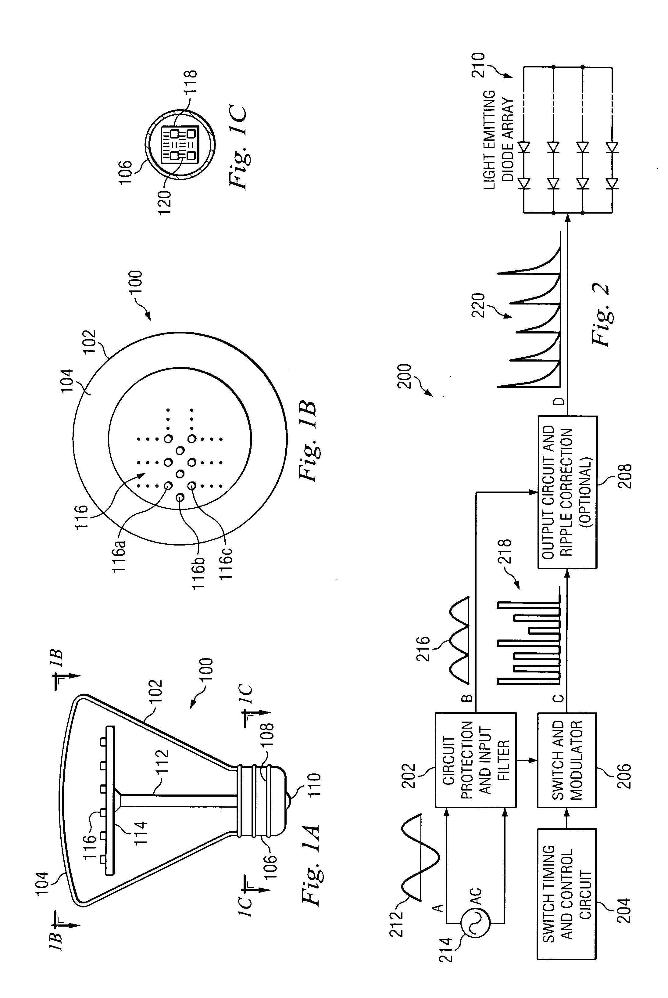
[0027]FIG. 1A is an illustration showing an exemplary electronic light generating element light bulb (“electronic light bulb”). The electronic light bulb 100 includes a housing formed of a tapered wall 102 and an outer cap 104. Although shown as a tapered wall 102, it should be understood that other non-tapered or more tapered configurations maybe utilized in forming the housing of the electronic light bulb 100. In one embodiment, the outer cap 104 is translucent. Alternatively, the outer cap 104 may be clear. Still yet, in another embodiment, the outer cap 104 may be formed of a lens that focuses, defocuses, diffuses, narrows, broadens, or performs some other optical function to the light being generated by electronic light generating elements within the electronic light bulb 100. The housing may further include a base 106 that engages or is coupled to the outer wall 102. The base 106 may be formed as a “Edison base” for connection to a conventi...


PUM


Abstract

The present system for driving an electronic light generating element, includes: (i) input terminals, (ii) an input circuit coupled to the input terminals and operable to convert a sinusoidal signal to a signal independent of negative current attributes, (iii) a switch control circuit coupled to the input circuit and operable to generate a switching signal having pulses, and (iv) a switching element coupled to the input circuit and the switch control circuit. The switching element is operable to generate an output signal formed as a series of bursts having peak amplitudes above a maximum forward current rating for a duty cycle less than a maximum operating duty cycle over which an electronic light generating element may be catastrophically damaged in response to the signal independent of negative current attributes and switching being applied to the switching element. The output signal is applied to the electronic light generating element to produce light.

Description

CROSS REFERENCE TO RELATED APPLICATIONS [0001] This application claims priority from co-pending U.S. Provisional Patent Application Ser. No. 60 / 565,268 titled “Improved Electronic Light Generating Element Light Bulb” and filed 23 Apr. 2004, the entire teachings of which are herein incorporated by reference. In addition, this application is related to U.S. patent application titled “Lighting Element Using Electronically Activated Light Emitting Elements And Method Of Making Same,” U.S. patent application titled “light bulb having wide angle light dispersion and method of making same,” and U.S. patent application titled “Light Bulb Having Surfaces For Reflecting Light Produced By Electronic Light Generating Sources,” both filed on the same date hereof, the entire teachings of which are herein incorporated by reference.BACKGROUND OF THE INVENTION [0002] 1. Technical Field of the Invention [0003] The principles of the present invention are generally directed to a light bulb, and more pa...

Claims


Application Information

Patent Timeline
IPC IPC(8): F21K99/00H05B44/00H05B45/50H05B45/59
CPCF21Y2101/02H05B33/0818H05B33/0845H05B33/0857F21V3/02Y02B20/19Y02B20/383F21K9/13H05B33/0887F21K9/23F21Y2115/10H05B45/50H05B45/10H05B45/20H05B45/327Y02B20/00Y02B20/30H05B45/56H05B45/3725H05B45/59
Inventor MAXIK, FREDRIC
Owner LIGHTING SCI GROUP
Why Eureka
Try Eureka