Proximity measuring apparatus

a technology of measuring apparatus and proximal beam, which is applied in the direction of multiplex communication, using reradiation, instruments, etc., can solve the problems of complex and potentially misleading echo radiation to the system, unreliability, and interference risk of several vehicles

Inactive Publication Date: 2003-09-02
QINETIQ LTD
View PDF13 Cites 342 Cited by
  • Summary
  • Abstract
  • Description
  • Claims
  • Application Information

AI Technical Summary

Problems solved by technology

(ii) when a plurality of vehicles each incorporate the system, there is a risk of interference between several the vehicles when operating simultaneously within range of one another; and
(iii) spurious multipath reflections from roadside stationary objects give rise to complex and potentially misleading echo radiation to the system.
However, this is potentially unreliable, especially when there are numerous vehicles each incorporating and using the system within range of one another.
For example, a problem arises when a series of vehicles each incorporating the system travel in convoy in an identical direction; because the systems installed in the vehicles are orientated in an identical bearing, their systems operate at identical frequencies such that mutual interaction of the systems can occur giving rise to a risk of erroneous proximity measurement.
Moreover, on account of the number of vehicles presently in use in the world, it is not feasible to allocate a unique radiation frequency band for each vehicle; problems of interference and interaction between systems in the prior art cannot therefore be ameliorated.
A problem arises in a scenario

Method used


Image

  • Proximity measuring apparatus
  • Proximity measuring apparatus
  • Proximity measuring apparatus

Examples


Embodiment Construction

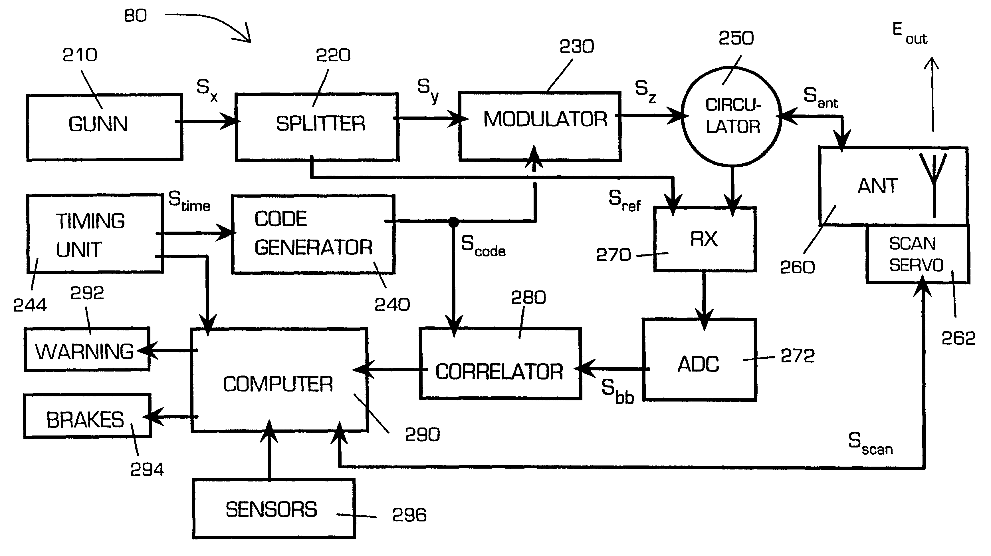
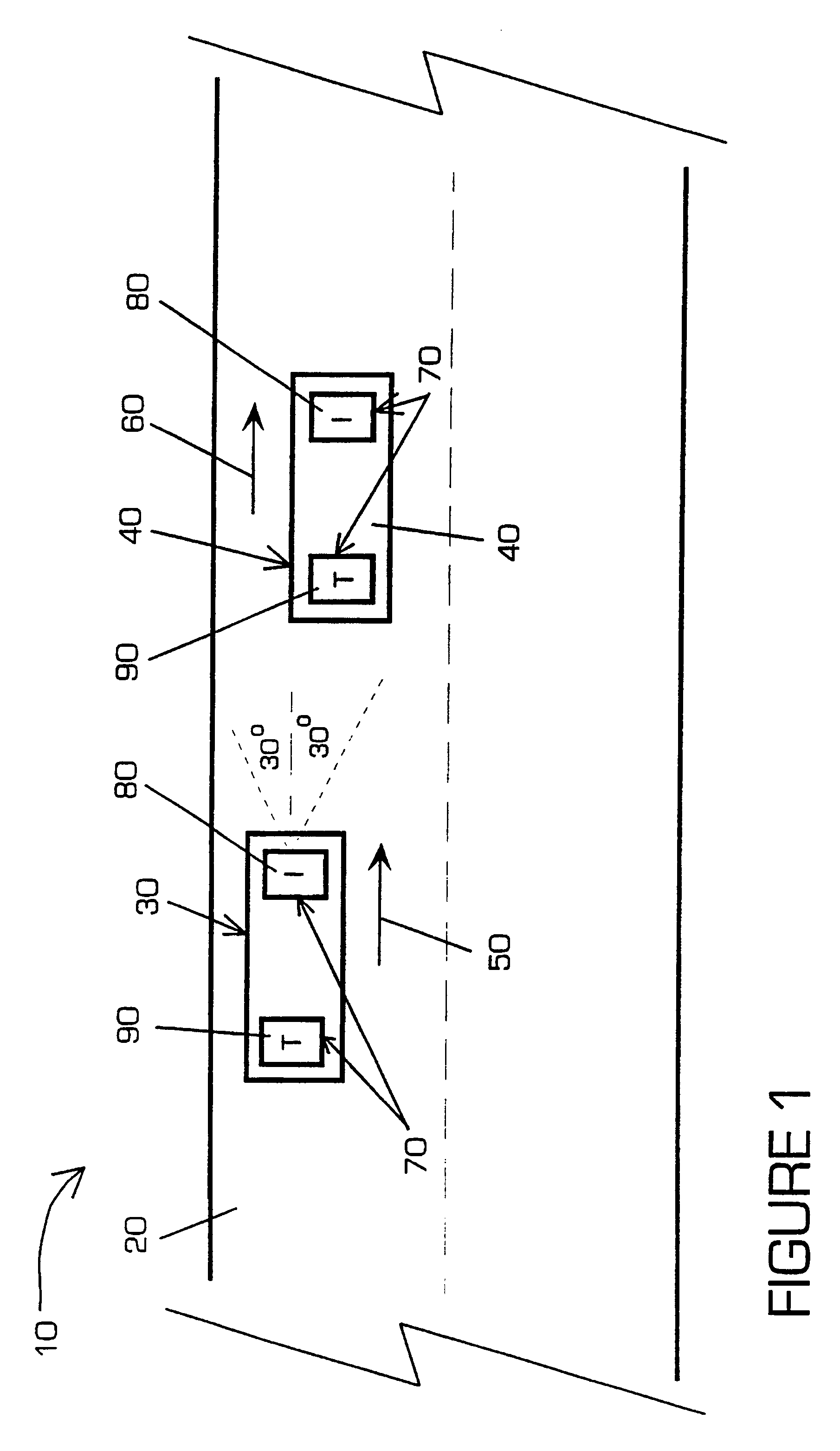
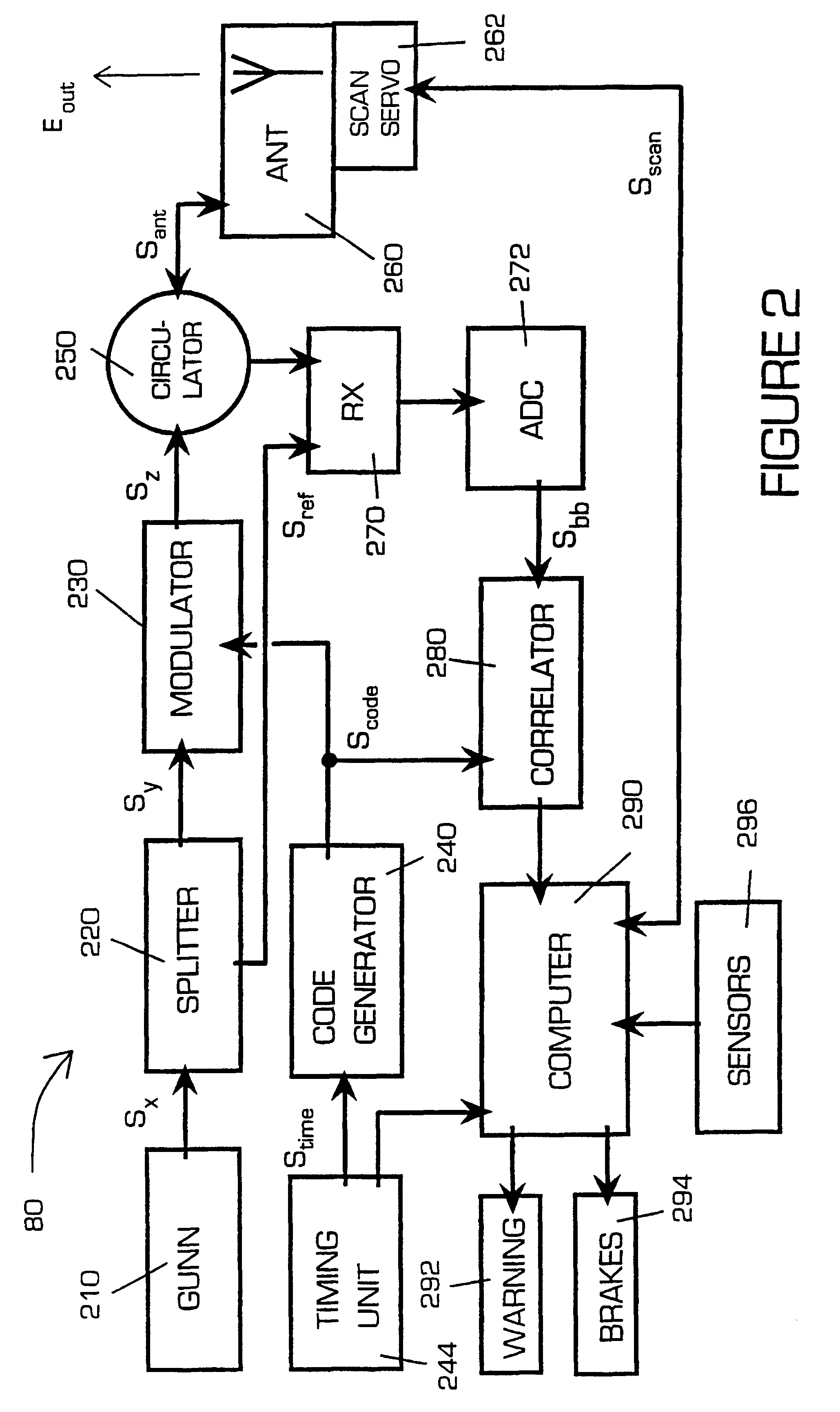
Referring to FIG. 1, there is shown a section of road indicated generally by 10. The section 10 includes a carriageway 20. A first vehicle 30 and a second vehicle 40 are illustrated travelling along the carriageway 20 in directions indicated by arrows 50, 60 respectively. The first vehicle 30 is shown travelling a short distance of 10 m behind the second vehicle 40. Each vehicle 30, 40 incorporates a proximity measuring apparatus of the invention indicated generally by 70. Each apparatus 70 comprises a radar interrogator (I) 80 and a transponder (T) 90. Each interrogator 80 and each transponder 90 is mounted in a frontal region and a rear region respectively of its associated vehicle 30, 40.

The interrogator 80 incorporates an antenna (not shown in FIG. 1) which has an aperture of 100 mm diameter. The antenna provides a directional polar gain response comprising a direction of enhanced gain; this direction will be referred to as its mainbeam direction. The antenna is arranged to emit...


PUM


Abstract

A proximity measuring apparatus (70) comprises an interrogator (80) for generating an interrogation signal encoded with a reference signature code comprising concatenated codes and emitting it as interrogating radiation. It also incorporates a transponder (90) for receiving the interrogating radiation, demodulating it to extract its signature code and then remodulating it after a delay period to provide a signal for reemission as return radiation therefrom. The interrogator (80) receives return radiation at its antenna (260) and demodulates it to extract its signature code and then correlates the code with the reference code to determine mutual correlation thereof. The interrogator (80) incorporates a computer (290) for controlling a scan direction of the antenna (260) and for measuring time delay between emission of the interrogating radiation therefrom and receipt of corresponding return radiation. The computer (290) computes distance and relative bearing of a transponder (90) providing the return radiation from the scan direction and the time delay. The apparatus (70) may be used for improving road vehicle safety.

Description

1. Field of the InventionThe present invention relates to a proximity measuring apparatus, and more particularly but not exclusively to an apparatus for incorporation into road vehicles for measuring their mutual proximity.2. Discussion of Prior ArtProximity measuring apparatus are well known. They are incorporated, for example, into vehicles for providing information regarding their positions relative to one another.One example of a proximity measuring apparatus is a road vehicle Doppler radar system. In use, the system is mounted onto a road vehicle and emits interrogating radiation towards other road vehicles which reflect the radiation as echo radiation back to the system for analysis therein to determine collision risk of the other vehicles to the system. A proximity measuring apparatus implemented as a microwave Doppler radar anticollision system is described in a United Kingdom patent application GB 96 02250.4.A number of problems are encountered with the system described in ...

Claims


Application Information

Patent Timeline
IPC IPC(8): G01S13/00G01S13/82G08G1/16H04J13/00G01S13/32G01S13/74G01S13/93
CPCG01S13/825G08G1/163H04J13/0029H04J13/107G01S13/325
Inventor DEADMAN, HARRY A
Owner QINETIQ LTD
Why Eureka
Try Eureka