Engine Mount For an Aircraft, to be Placed Between an Engine and an Engin Mounting Structure

a technology for aircraft and mounting structures, which is applied in the direction of machines/engines, mechanical equipment, transportation and packaging, etc., can solve the problems of difficult installation of attachments, difficulty in accessing the forward end of pins passing through the clevis, and difficulty in reducing the safety of collisions, so as to reduce the risk of collisions, increase the longitudinal separation, and increase the longitudinal separation

Active Publication Date: 2008-07-03
AIRBUS OPERATIONS (SAS)
View PDF11 Cites 20 Cited by
  • Summary
  • Abstract
  • Description
  • Claims
  • Application Information

AI Technical Summary

Benefits of technology

[0023]Therefore, it must be understood that the inclined arrangement of the clevis advantageously reduces risks of collision, but can increase the longitudinal separation between the EMS supporting this attachment and the fan casing, the inclination of the clevis obviously being contrary to the continuous search for compactness. Nevertheless, this increase in longitudinal separation related to the inclination of the clevis may be largely compensated by the presence of fixing devices at each closed ring, which no longer require access between the forward end of the connecting pins and the fan casing.
[0024]In other words, this preferred configuration implies that the fan casing can be moved significantly closer to the lower part of the forward attachment, without causing any risk of collision between the upper part of the casing and the upper part of the forward attachment located further back than the lower part of this same attachment.

Problems solved by technology

Although this technical solution is extremely widespread in the engine attachments field, it does have a major disadvantage which is that access to the ends of the pin becomes increasingly difficult, particularly due to the trend towards increasing compactness for such engine assemblies.
This disadvantage inevitably leads to difficulties in installing these attachments, that are penalising in terms of cost and time.
For example, this problem may arise particularly in the case of a forward attachment in which access to the forward end of the pins passing through the clevis may be extremely limited due to the presence of the engine fan casing, which is located so close to this end of the pin that it is practically impossible to manipulate the required tools to fix this pin.

Method used


Image

  • Engine Mount For an Aircraft, to be Placed Between an Engine and an Engin Mounting Structure
  • Engine Mount For an Aircraft, to be Placed Between an Engine and an Engin Mounting Structure
  • Engine Mount For an Aircraft, to be Placed Between an Engine and an Engin Mounting Structure

Examples


Embodiment Construction

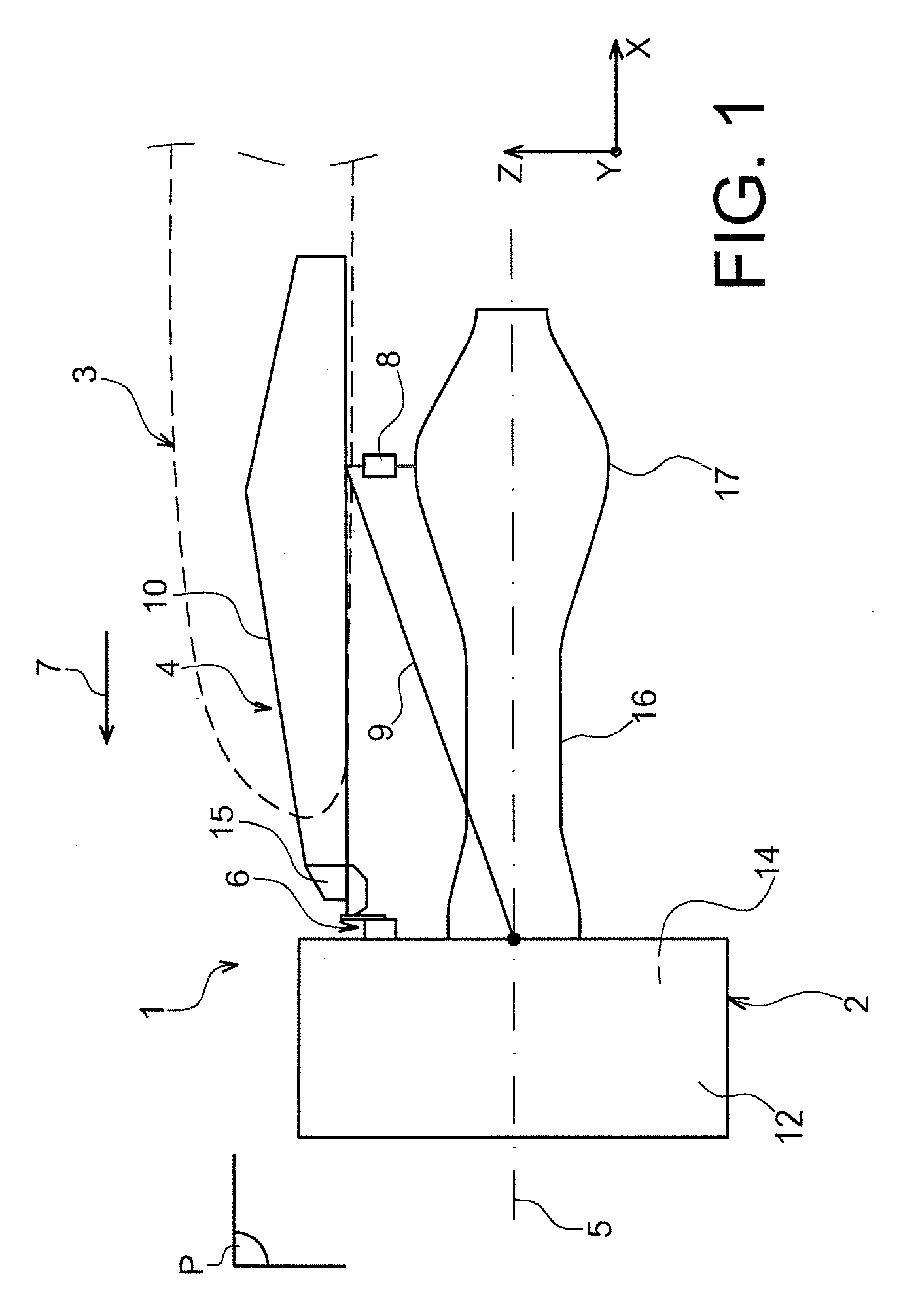
[0033]FIG. 1 shows an aircraft engine assembly 1 designed to be fixed under a wing of this aircraft (shown only diagrammatically and marked as numeric reference 3), this assembly 1 being in the form of a preferred embodiment of this invention.

[0034]Globally, the engine assembly 1 is composed of an engine such as a turbojet 2, an EMS 4 and a plurality of engine attachments 6, 8, 9 inserted between a rigid structure 10 of the EMS 4 and the turbojet 2. For guidance, note that the assembly 1 is designed to be surrounded by a pod (not shown) and the EMS 4 is fitted with another series of attachments (not shown) to suspend this assembly 1 under the aircraft wing.

[0035]In all of the following description, by convention, X is the longitudinal direction of the EMS 4 that can be considered to be the same as the longitudinal direction of the turbojet 2, this direction X being parallel to the longitudinal axis 5 of this turbojet 2. Furthermore, Y is the direction transverse from the EMS 4 and c...


PUM


Abstract

An aircraft engine attachment configured to be inserted between an engine and an EMS, the attachment including a clevis connected to a first fixing device including an end fitting with two arms and a pin passing through the clevis and the two arms, in each of which an orifice is formed including a first ring and a second ring respectively holding the pin. The first ring includes a bottom acting as a stop for a first end of the pin, and the first attachment device includes a mechanism to stop the pin in translation cooperating with a second end of the pin.

Description

TECHNICAL DOMAIN[0001]This invention relates in general to an aircraft engine attachment designed to be inserted between an engine and an <<EMS>> (Engine Mounting Structure), used to suspend the engine below the aircraft wing, or to mount this engine above this wing.[0002]The invention also relates to an aircraft engine assembly comprising an engine, an EMS and a plurality of engine attachments inserted between this EMS and the engine, this assembly being useable on any type of aircraft, for example of the type comprising turboshaft engines suspended from the wing, such as turbojets or turboprops.STATE OF PRIOR ART[0003]On existing aircraft, turboshaft engines are suspended below the wing by complex attachment devices (also called EMSs) through a plurality of engine attachments fixed to the same EMS.[0004]Such an EMS is designed to transmit forces generated by the associated engine to the structure of this aircraft, and is also used for the transfer of fuel, electrical a...

Claims


Application Information

Patent Timeline
Patent Type & Authority Applications(United States)
IPC IPC(8): F02C7/20B64D27/00
CPCB64D27/26F16C11/0614F16C11/0695F16C2326/43
Inventor AUDART-NOEL, VIRGINIEGARDES, PASCAL
Owner AIRBUS OPERATIONS (SAS)
Why Eureka
Try Eureka