Detection of fluids in tissue

a technology of tissue fluid and detection field, applied in the field of tissue fluid detection, can solve the problems of blood collecting and clotting (hematoma), patient does not remember, and the head injury may have been so minor, and achieve the effect of low profil

Inactive Publication Date: 2006-10-17
BAYER HEALTHCARE LLC
View PDF51 Cites 339 Cited by
  • Summary
  • Abstract
  • Description
  • Claims
  • Application Information

AI Technical Summary

Benefits of technology

[0036]In the case of extravasation, the present invention easily affords the ability to detect extravasation at the injection site and/or any position or site remote from an injection site, for example, along a path of potential extravasation. In that regard, extravasation sometimes occurs at a site remote from the catheter insertion point (that is, the injection site). Multiple energy sources and/or multiple sensors may be positioned along a path of potential extravasation.
[0037]Numerous other advantages are afforded by the apparatuses, systems and methods of the present invention as compared to curren

Problems solved by technology

Moreover, bleeding (hemorrhage) can cause blood to collect and clot (hematoma).
Such a head injury may have been so minor that the patient does not remember it.
It is often difficult to detect hematomas, particularly when the hematoma occurs well after the time of an injury.
Extravasation can be caused, for example, by rupture or dissection of fragile vasculature, valve disease, inappropriate needle placement, or patient movement resulting in the infusing needle being pulled from the intended vessel or causing the needle to be pushed through the wall of the vessel.
High injection pressures and/or rates of some modem procedures can increase the risk of extravasation.
Extravasation can cause serious injury to patients.
In that regard, certain injection fluids such as contrast media or chemotherapy drugs can be toxic to tissue.
Unfortunately, each of these automated methods of

Method used


Image

  • Detection of fluids in tissue
  • Detection of fluids in tissue
  • Detection of fluids in tissue

Examples


experimental examples

[0114]1. Inorganic Phantom Experiments

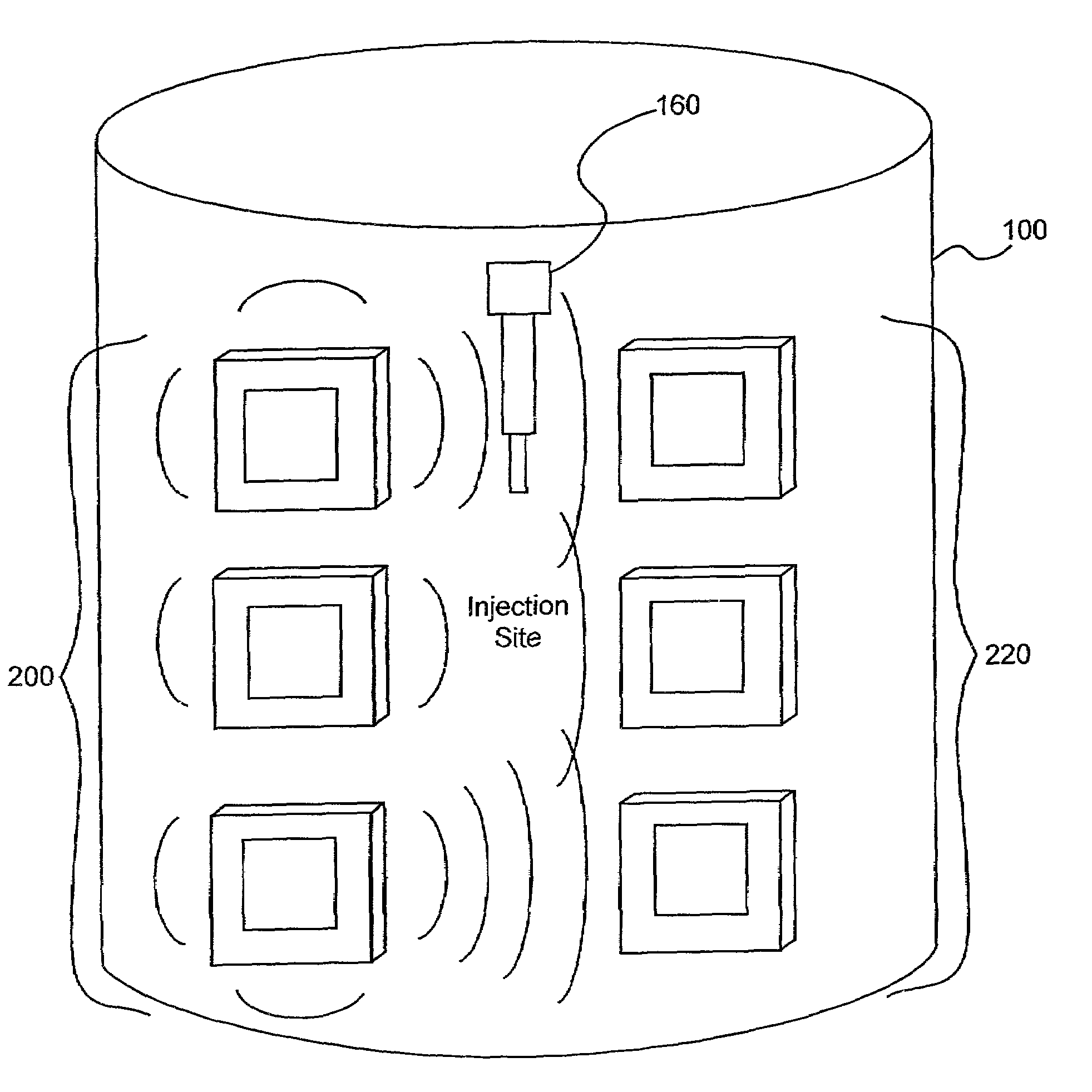
[0115]Several experiments demonstrating the present invention were carried out using single and dual microstrip patch antenna configurations and an inorganic phantom to represent human tissue. Such inorganic phantoms provide the opportunity to accurately control both the position and amount of a simulated extravasation in an environment of generally known and simple dielectric properties (as compared to human tissue).

[0116]The microstrip antennae used in the studies were designed using Finite Difference Time Domain (FDTD) modeling techniques and were etched and fabricated in the laboratory. Standard equations, (generally available for well-understood geometries), were used to determine approximate dimensions required for the resonant structures of the various antennae studied in the present invention. Following that, substrate thickness was chosen to be a fraction of the wavelength corresponding to the primary resonant mode of the resonant struc...


PUM


Abstract

A method of detecting a change (that is, an increase or a decrease) in the level of fluid in tissue in a first area of a body includes the steps of: applying electromagnetic energy, preferably in the frequency range of approximately 300 MHz to approximately 30 GHz, to a first volume of the body; measuring a resultant or returned signal; comparing the signal to a reference signal to determine if the fluid level in the tissue has changed. In one embodiment, the method detects changes in the level of fluid in tissue of a body by applying electromagnetic energy to a first volume of the body over a period of time (for example, using an antenna or antennae); measuring a resultant signal or a signal returned from the tissue; and comparing the signal to a reference signal to determine if a level of fluid in the tissue has changed during the period of time.

Description

CROSS-REFERENCE TO RELATED APPLICATIONS[0001]This application claims the benefit of U.S. Provisional Patent Application Ser. No. 60 / 308,012, filed Jul. 26, 2001, the disclosure of which is incorporated herein by reference. This application is related to an application, filed on even date herewith, entitled ELECTROMAGNETIC SENSORS FOR BIOLOGICAL TISSUE APPLICATIONS AND METHODS FOR THEIR USE, also claiming priority to U.S. Provisional Patent Application Ser. No. 60 / 308,012, filed Jul. 26, 2001, the disclosure of which is also incorporated herein by reference.BACKGROUND OF THE INVENTION[0002]The present invention relates generally to the detection of fluids in tissue, and, more particularly, to apparatuses, systems and methods for detection of changed, elevated or abnormal fluid levels in tissue.[0003]Changed, elevated or abnormal fluid levels in living tissue can result from a number of physiological conditions. For example, edema is an abnormal accumulation of watery fluid in the int...

Claims


Application Information

Patent Timeline
IPC IPC(8): A61B5/117A61B5/103A61B5/05A61B5/053A61M5/168A61N2/04G01N22/00H01Q1/27H01Q1/40H01Q9/04H01Q13/18H01Q21/06H01Q21/20
CPCA61B5/05A61B5/0507A61B5/0537A61B5/411A61B5/4878A61M5/16836G01N22/00H01Q1/273H01Q1/40H01Q9/0407H01Q9/0414H01Q13/18H01Q21/06H01Q21/065H01Q21/20A61B2562/02A61B2562/046A61B2562/143
Inventor BOUTON, CHADHIRSCHMAN, ALAN D.
Owner BAYER HEALTHCARE LLC
Why Eureka
Try Eureka