Gear pump and liquid injection apparatus

a liquid injection apparatus and gear pump technology, applied in the direction of positive displacement liquid engines, piston pumps, liquid fuel engines, etc., can solve the problems of increasing manufacturing costs, manufacturing steps, and low liquid pumping efficiency,

Inactive Publication Date: 2005-10-27
SEIKO EPSON CORP
View PDF4 Cites 33 Cited by
  • Summary
  • Abstract
  • Description
  • Claims
  • Application Information

AI Technical Summary

Benefits of technology

[0010] A further aspect of the present invention is a gear pump for discharging fluid. The gear pump is provided with a housing defining an accommodation chamber including an opening. The fluid flows into the accommodation chamber at a suction position and flows out of the accommodation chamber at a discharge position. A drive gear and a driven gear are arranged in the accommodation chamber to transfer the fluid from th

Problems solved by technology

This would lower the pumping efficiency of the liquid.
However, the machining of the gears 103 and 104 and

Method used


Image

  • Gear pump and liquid injection apparatus
  • Gear pump and liquid injection apparatus
  • Gear pump and liquid injection apparatus

Examples


first embodiment

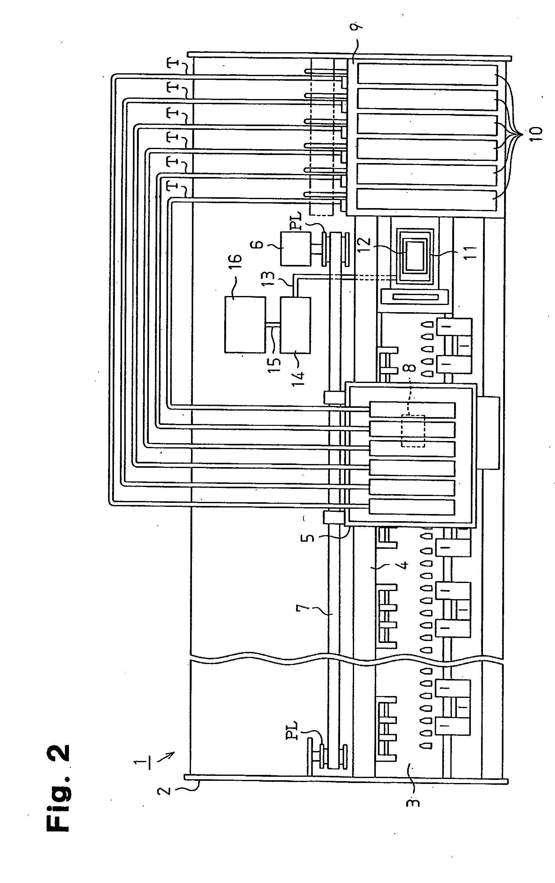
[0033] A liquid injection apparatus incorporating a gear pump according to the present invention will now be described. FIG. 2 is a schematic plan view of an ink jet recording device (printer) serving as the liquid injection apparatus.

[0034] The printer includes a frame 2 having a generally box-like shape. A platen 3 is arranged in the frame 2 and a recording paper (not shown) serving as a target is fed to the platen 3 by a paper feeding mechanism (not shown).

[0035] A guide member 4 is arranged on the frame 2 so as to be parallel to the longitudinal direction of the platen 3. A carriage 5 movable along the guide member 4 is supported by the guide member 4. A carriage motor 6 is attached to the frame 2. The carriage motor 6 drives the carriage 5 with a timing belt 7 wound along a pair of pulleys PL. When the carriage motor 6 is driven, the driving force of the carriage motor 6 is transmitted to the carriage 5 by the timing belt 7, and the carriage 5 reciprocates in a direction paral...

second embodiment

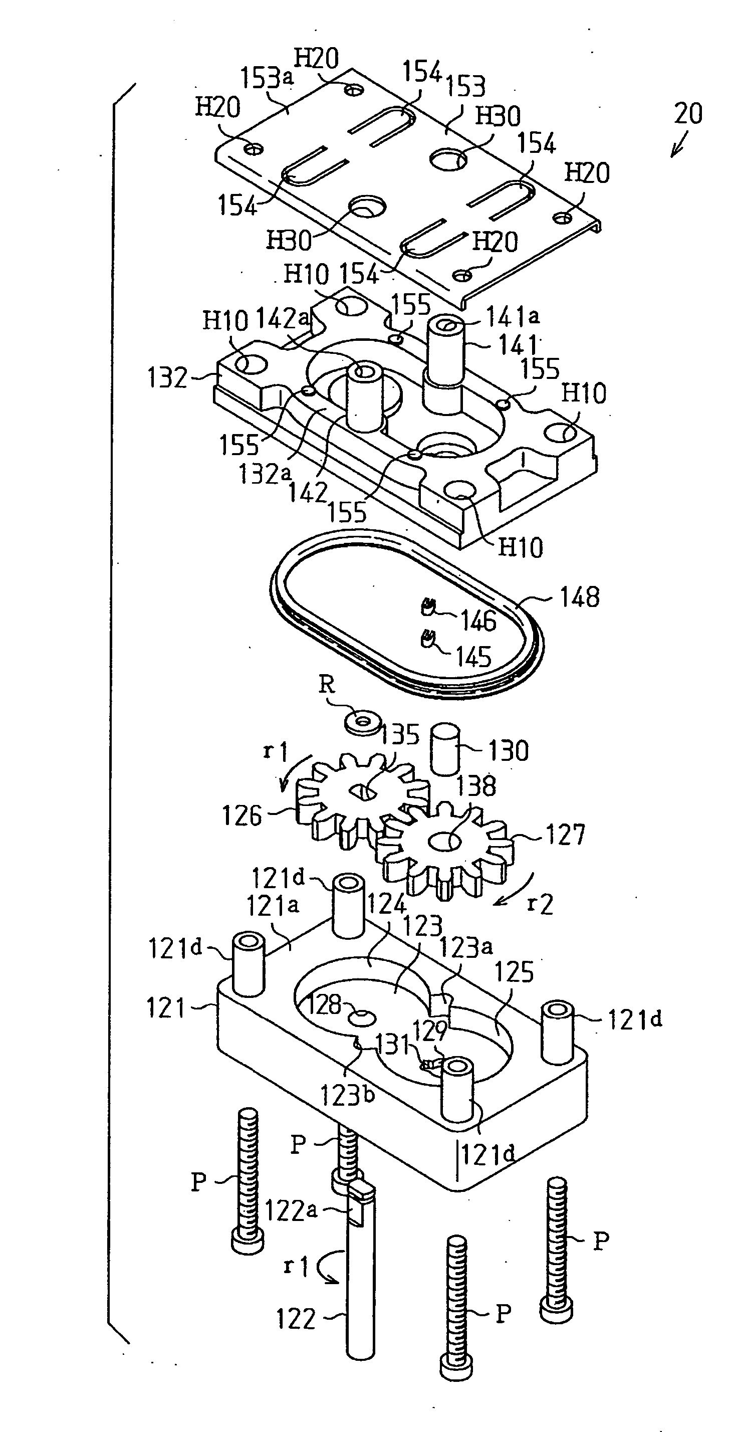
[0063] A gear pump 20 according to the present invention will now be described with reference to FIGS. 8 to 23.

[0064]FIG. 8 is an entire perspective view of the gear pump 20, and FIG. 9 is an exploded perspective view of the gear pump 20. As shown in FIG. 8, the gear pump 20 includes a housing 21, an upper seal assembly 21U arranged on the upper surface side of the housing 21, and a lower seal assembly 21L arranged on the lower surface side of the housing 21. A drive shaft 22 is projected out of the lower seal assembly 21L. The drive shaft 22 is coupled to a drive mechanism of the pump unit (see FIG. 2) and is rotated by the drive of the drive motor.

[0065] The housing 21 will be described in accordance with FIGS. 10 to 13. FIGS. 10 and 11 are perspective views showing the housing 21 and the drive gear 35 and the driven gear 40 accommodated in the housing 21. FIG. 12 is a plan view showing the housing 21 accommodating the drive gear 35 and the driven gear 40, and FIG. 13 is a bottom...


PUM


Abstract

A high-performance gear pump that does not require highly accurate machining is disclosed. The gear pump includes a housing having an accommodation chamber. A drive gear and a driven gear are positioned in contact with an inner surface of the accommodation chamber. The drive shaft is loosely received by the shaft hole of the drive gear, and the driven shaft is loosely received by the shaft support formed in the housing and the cover.

Description

CROSS-REFERENCE TO RELATED APPLICATIONS [0001] This application is based upon and claims the benefit of priority from prior Japanese Patent Application No. 2003-406044, filed on Dec. 4, 2003, and Japanese Patent Application No. 2004-116832, filed on Apr. 12, 2004, the entire contents of which are incorporated herein by reference. BACKGROUND OF THE INVENTION [0002] The present invention relates to a gear pump and a liquid injection apparatus incorporating a gear pump. [0003] A gear pump is generally superior to other types of pumps in that it has a simple configuration. FIG. 1 shows a conventional gear pump 100. The gear pump 100 has a drive gear 103 and a driven gear 104 accommodated in an accommodation chamber 102, which is formed in a housing 101 (refer to, for example, Japanese Laid-Open Patent Publication No. 8-093657). The drive gear 103 and the driven gear 104 are rotatably supported by rotation shafts 105 and 106, respectively. A suction chamber 110 and a discharge chamber 11...

Claims


Application Information

Patent Timeline
IPC IPC(8): F04C2/08F04C2/18
CPCF04C2/086F04C2230/60F04C2/18F04C2/14
Inventor IWASAKI, MITSUTAKA
Owner SEIKO EPSON CORP
Why Eureka
Try Eureka