Gear pump and liquid injection apparatus
a liquid injection apparatus and gear pump technology, applied in the direction of machines/engines, liquid fuel engines, positive displacement liquid engines, etc., can solve the problems of increasing manufacturing costs, manufacturing steps, and low liquid pumping efficiency,
- Summary
- Abstract
- Description
- Claims
- Application Information
AI Technical Summary
Benefits of technology
Problems solved by technology
Method used
Image
Examples
first embodiment
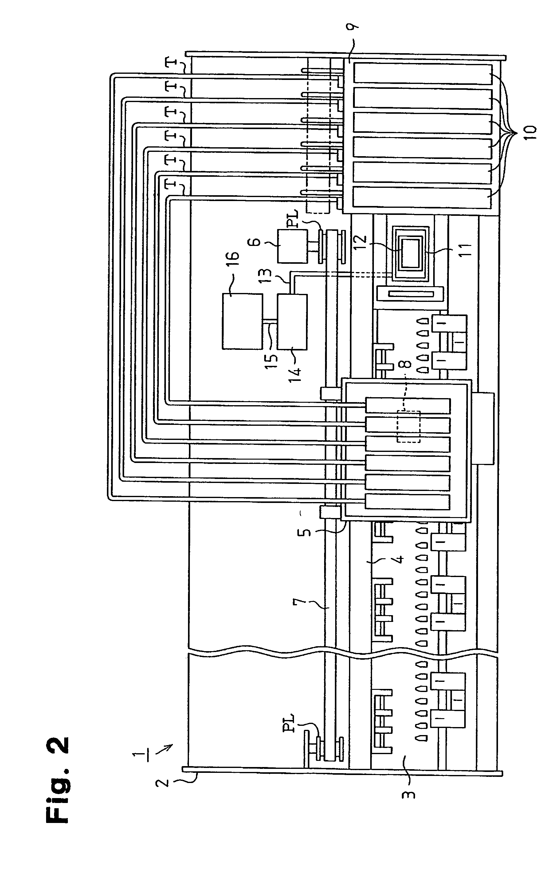
[0033]A liquid injection apparatus incorporating a gear pump according to the present invention will now be described. FIG. 2 is a schematic plan view of an ink jet recording device (printer) serving as the liquid injection apparatus.
[0034]The printer includes a frame 2 having a generally box-like shape. A platen 3 is arranged in the frame 2 and a recording paper (not shown) serving as a target is fed to the platen 3 by a paper feeding mechanism (not shown).
[0035]A guide member 4 is arranged on the frame 2 so as to be parallel to the longitudinal direction of the platen 3. A carriage 5 movable along the guide member 4 is supported by the guide member 4. A carriage motor 6 is attached to the frame 2. The carriage motor 6 drives the carriage 5 with a timing belt 7 wound along a pair of pulleys PL. When the carriage motor 6 is driven, the driving force of the carriage motor 6 is transmitted to the carriage 5 by the timing belt 7, and the carriage 5 reciprocates in a direction parallel ...
second embodiment
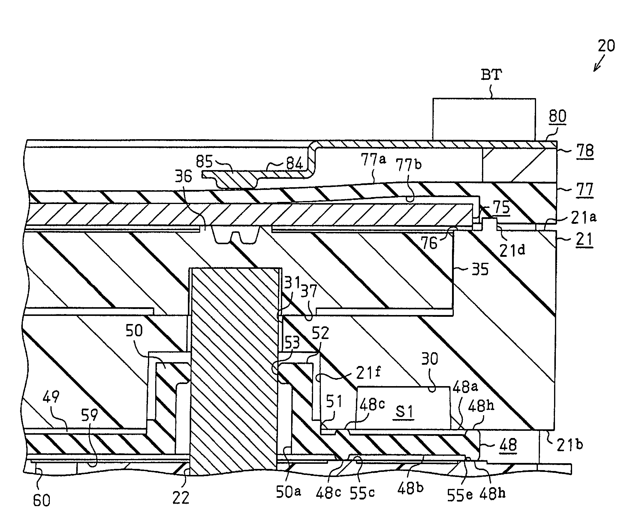
[0063]A gear pump 20 according to the present invention will now be described with reference to FIGS. 8 to 23.
[0064]FIG. 8 is an entire perspective view of the gear pump 20, and FIG. 9 is an exploded perspective view of the gear pump 20. As shown in FIG. 8, the gear pump 20 includes a housing 21, an upper seal assembly 21U arranged on the upper surface side of the housing 21, and a lower seal assembly 21L arranged on the lower surface side of the housing 21. A drive shaft 22 is projected out of the lower seal assembly 21L. The drive shaft 22 is coupled to a drive mechanism of the pump unit (see FIG. 2) and is rotated by the drive of the drive motor.
[0065]The housing 21 will be described in accordance with FIGS. 10 to 13. FIGS. 10 and 11 are perspective views showing the housing 21 and the drive gear 35 and the driven gear 40 accommodated in the housing 21. FIG. 12 is a plan view showing the housing 21 accommodating the drive gear 35 and the driven gear 40, and FIG. 13 is a bottom vi...
PUM
 Abstract
Description
Claims
Application Information
 - R&D
- Intellectual Property
- Life Sciences
- Materials
- Tech Scout
- Unparalleled Data Quality
- Higher Quality Content
- 60% Fewer Hallucinations
Browse by: Latest US Patents, China's latest patents, Technical Efficacy Thesaurus, Application Domain, Technology Topic, Popular Technical Reports.
© 2025 PatSnap. All rights reserved.Legal|Privacy policy|Modern Slavery Act Transparency Statement|Sitemap|About US| Contact US: help@patsnap.com


