Hair comb

Inactive Publication Date: 2005-11-03
WAHL CLIPPER
View PDF26 Cites 13 Cited by
  • Summary
  • Abstract
  • Description
  • Claims
  • Application Information

AI Technical Summary

Benefits of technology

[0011] The center section can have an opening for a finger. In this manner, the comb can easily be twirled around the finger to change from the fine teeth to the coarse teeth and vice versa. Also, the elongated ends of the comb can be offset from the center line, which makes the comb easier to grasp.
[0012] In other aspects of the invention, at le

Problems solved by technology

A user typically holds a conventional comb at the back of the devi

Method used


Image

  • Hair comb
  • Hair comb
  • Hair comb

Examples


Embodiment Construction

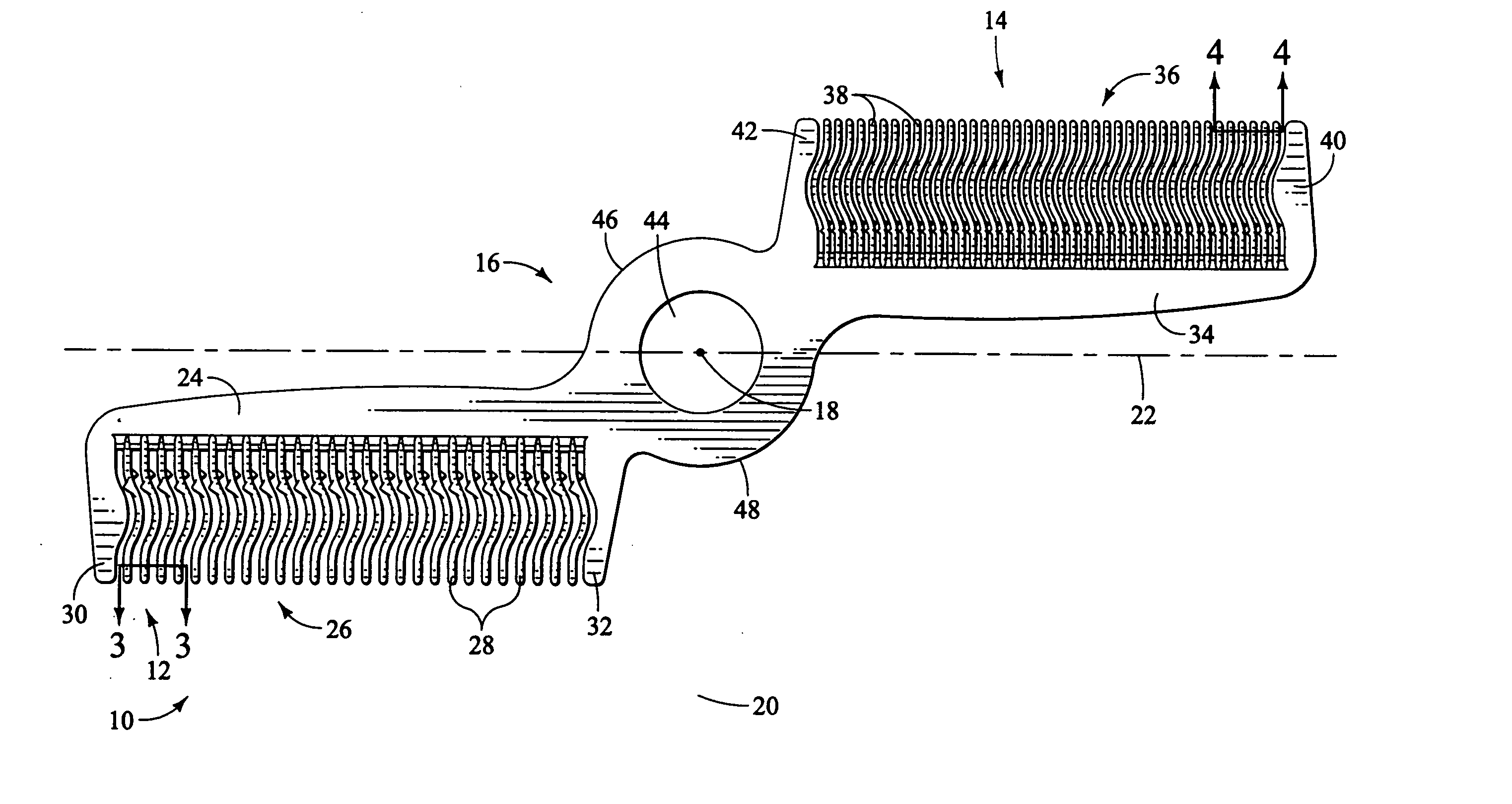
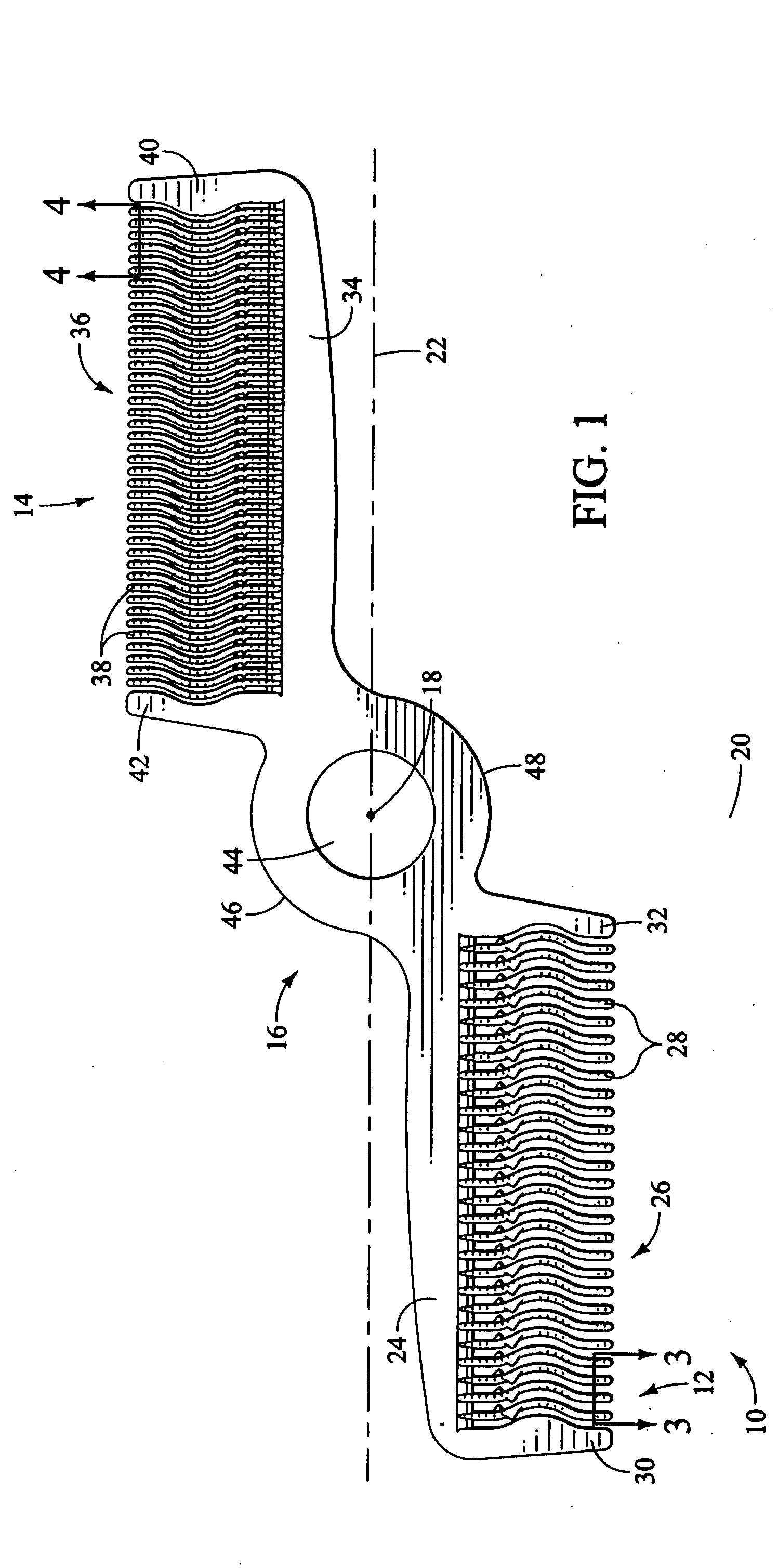
[0017] As seen in FIG. 1, a hand-held comb 10 is a generally flat, elongated device having a first end portion 12, a second end portion 14, and a center portion 16. The comb 10 is generally symmetrical about an origin 18, a vertical axis 20 and a horizontal axis 22. This axis 22 forms a longitudinal center of the comb 10.

[0018] The first end portion 12 has an inner edge 24 along the horizontal axis 22, and an outer edge 26 opposite the edge 24. A plurality of first comb teeth 28 extend away from the axis 22 from the first edge 24 to the edge 26. The edge 24 has sufficient structure to give the comb and the comb teeth strength. A relatively wide end piece 30 is provided at the outer end of the first end portion 12, and another end piece 32 is provided at the inner first end of the end portion 12. The end piece 32 is adjacent the center section 16.

[0019] The second end portion 14 has an inner end portion 34 along the horizontal axis 22, and an outer edge 36 opposite the edge portion...


PUM


Abstract

A hand-held comb has a set of fine teeth and a set of coarse teeth joined by a center section. The center section preferably has an opening large enough for a finger. The fine teeth and coarse teeth extend in opposite directions away from a longitudinal axis. Some or all of the teeth can have at least one undulation, to remove loose hair and at least some of the teeth can have barbs, to remove partially cut hair strands. The teeth can have sharp edges, which also remove partially cut hair strands.

Description

[0001] This invention relates to hair combs, and more particularly, to hair combs having undulating teeth and / or barbs on the teeth, a finger ring for ease of use, and fine and coarse comb teeth oriented in opposite directions. BACKGROUND OF THE INVENTION [0002] Conventional combs are sometimes used to remove loose hair after a hair cut, but they leave some cut hair in the head. Thus, there is a need for combs that better remove more of such loose hair. [0003] When a person's hair is cut, half cut hair strands are typically present after the hair cut, which is not preferred. There is also a need for combs that can remove half cut hair strands. [0004] A conventional hair comb has a set of straight fine comb teeth, and a separate set of coarse comb teeth immediately adjacent the fine teeth. All of the teeth are oriented in the same direction. A user typically holds a conventional comb at the back of the device and pinches the comb, which can be tiring and even cause strain. Thus, ther...

Claims


Application Information

Patent Timeline
IPC IPC(8): A45D24/00A45D24/04B26B19/20
CPCA45D24/04
Inventor EDDINGER, MICHAELNIELSEN, RAYMOND A.MELTON, SCOTT A.
Owner WAHL CLIPPER
Why Eureka
Try Eureka