Image output control device

a control device and image technology, applied in the direction of digital output to print units, instruments, digital computers, etc., can solve the problems of large processing load of the cpu in the image output control device, the inability of high speed printers to efficiently function at their high performance rate, and the only satisfactory color print currently produced

Inactive Publication Date: 2005-11-03
KONICA MINOLTA MEDICAL & GRAPHICS INC
View PDF4 Cites 2 Cited by
  • Summary
  • Abstract
  • Description
  • Claims
  • Application Information

AI Technical Summary

Benefits of technology

[0009] The present invention has been achieved to counter the above conditions. An object of the present invention is to provide an image output control device which is able to transfer printing image data of each image to a printer at a constant transfer rate. The objective of the present invention can be attained by the structures described below.

Problems solved by technology

Though the color proof requires faithful color reproduction of the original color printed matter, printers providing only satisfactory color prints are presently produced.
If the image output control device cannot secure a high output rate by which the image data of each image are continuously transferred to the printer at a constant transfer rate, then a high speed printer cannot efficiently function at its high performance rate.
Further, since the image output control device carries out the process for converting post script (PS) image data to image data suitable for printer outputting, such as bitmap (BMP) type (hereinafter referred to as printing image data), the CPU in the image output control device has large processing load.
Accordingly, in order to reduce the processing time, when the converting process of the image data as well as the transferring process of the printing image data is simultaneously performed, the CPU has a larger processing load, and it is very difficult to keep a constant transfer rate of the printing image data of each image.
Therefore, the frequency of use of the bus for controlling the transfer process to the printer is greatly limited, and it becomes more difficult to maintain a high transfer rate to the printer.

Method used


Image

  • Image output control device
  • Image output control device
  • Image output control device

Examples


Embodiment Construction

[0029] The embodiments of the image output control device related to the present invention will now be detailed referring to the drawings. Firstly, the structure of the image outputting system including the image output control device and the work flow employing the present system will be explained, after which the structure and the operation of the image output control device will be explained.

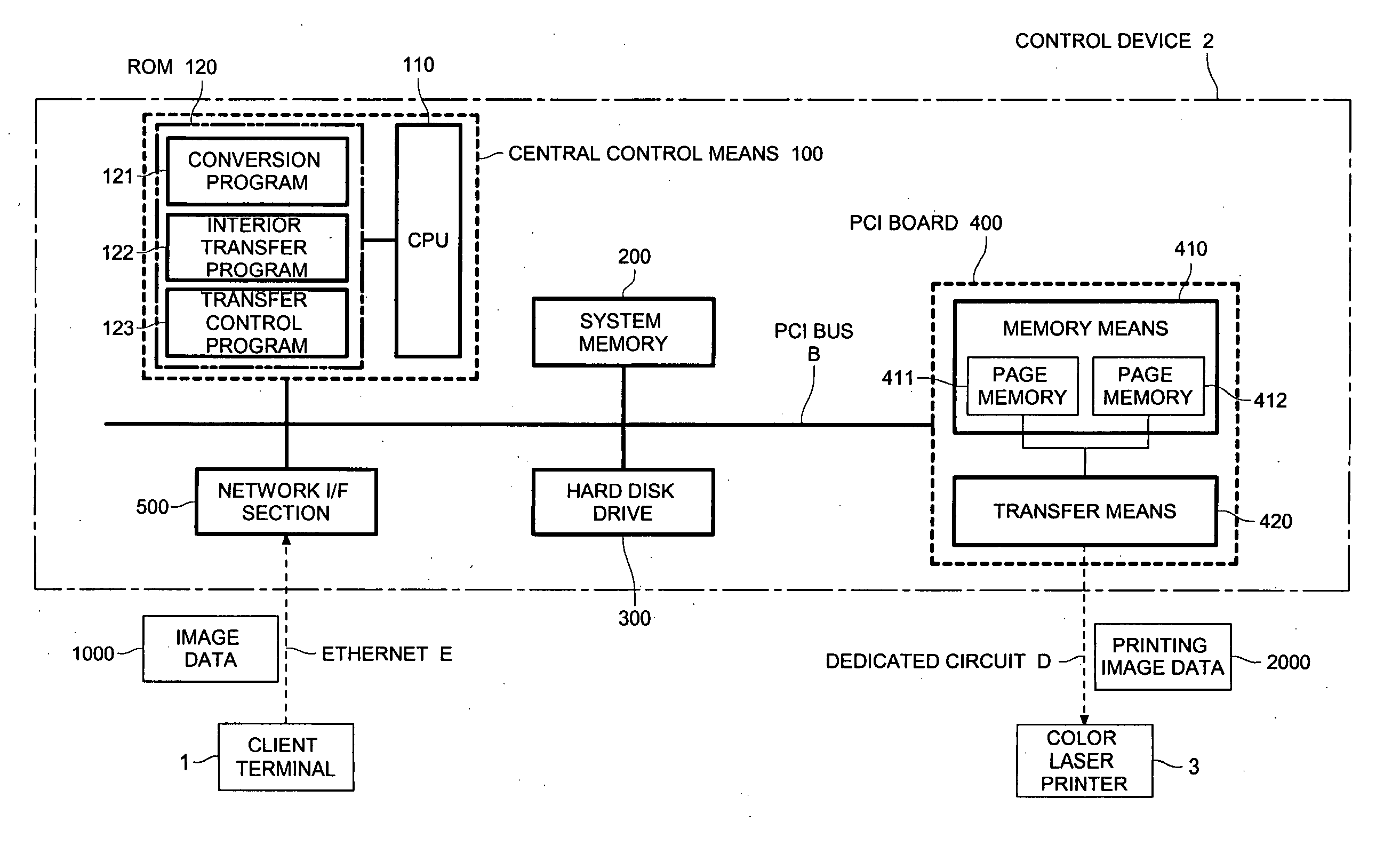
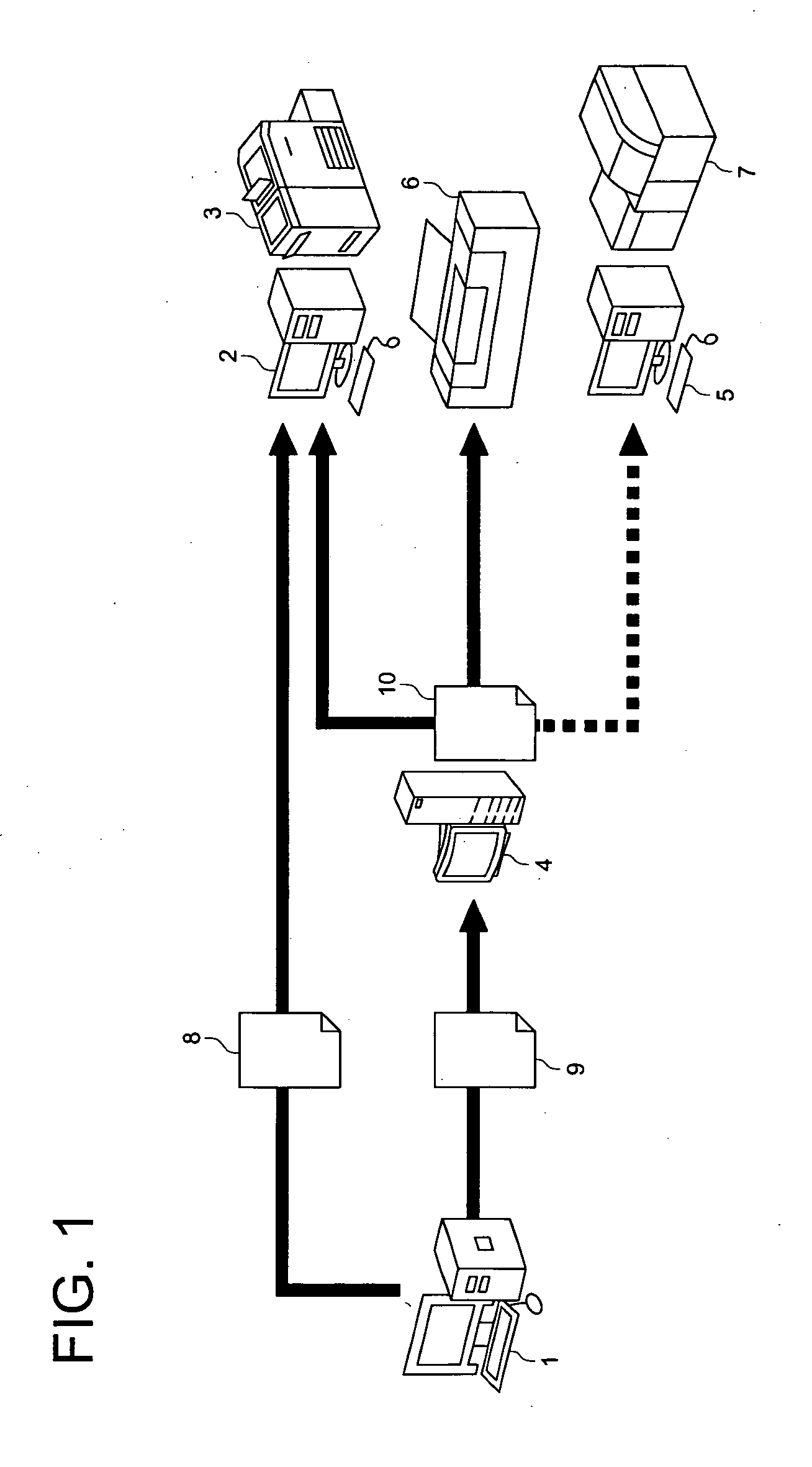
[0030]FIG. 1 shows a structure and work flow of an image output system including an image output control device. The image output system includes at least one set of client terminal 1, control device 2, color laser printer 3 (sometimes simply referred to as printer 3), RIP 4 used for CTP (which is raster image processor 4 used for the process of CTP, hereinafter referred to as “CTP-RIP 4”, CTP means “computer to plate”), DCP (digital color proof) control device 5, CTP 6 and DCP forming device 7, all of which are connected via a network.

[0031] Client terminal 1 is used for image editing (for...


PUM


Abstract

An image output control device, including a local bus, a central control section connected to the local bus, having, an image data conversion section for converting an image data, inputted from an outside of the image output control device, to a printing image data which is used when an exterior printing device prints out images, an interior transferring section for transferring the printing image data to a memory section so that the memory section stores the printing image data, and a transfer control section for outputting a control signal for transferring the printing image data in the memory section to the exterior printing device, the memory section connected to the local bus, for storing the printing image data, and the transfer section connected to the local bus, for receiving the control signal and transferring the printing image data in the memory section to the exterior printing device.

Description

[0001] This application is based on Japanese Patent Application No. 2004-133649 filed on Apr. 28, 2004, in Japanese Patent Office, the entire content of which is hereby incorporated by reference. BACKGROUND OF THE INVENTION [0002] The present invention relates to an image output control device which converts the image data inputted from the outside of the device and transfers it to a printer, and also controls the printing process being performed by the printer. Further, in order to optimize the output rate performance of the printer, the present invention relates to an image output control device structured so as to transfer the image data at a constant transfer rate. [0003] In recent years, color laser printers are expected to be used in various fields due to their high quality of color-printed results as well as due to their high output rate. One effective example in a new field is that color laser printers are applied to output color proofs of color print correction in the field...

Claims


Application Information

Patent Timeline
Patent Type & Authority Applications(United States)
IPC IPC(8): G06F3/12B41J5/30G06F15/00H04N1/00H04N1/32
CPCH04N1/00127H04N1/00204H04N2201/0039H04N1/324H04N1/00278
Inventor SUGITA, TSUYOSHI
Owner KONICA MINOLTA MEDICAL & GRAPHICS INC
Why Eureka
Try Eureka