Method and device of dynamic resource allocation in a wireless network

a wireless network and resource allocation technology, applied in the field of communication networks, can solve the problems of inability to reliably provide network as a wireless network transmission resource, transmission errors can occur on one or several data flows, etc., and achieve the effect of reducing the bandwidth allocated

Inactive Publication Date: 2005-11-10
MITSUBISHI ELECTRIC CORP
View PDF6 Cites 80 Cited by
  • Summary
  • Abstract
  • Description
  • Claims
  • Application Information

AI Technical Summary

Benefits of technology

[0024] and wherein the second subset comprises a rule for reducing the bandwidth allocated to data flows belonging to the second set of flow types compared to the bandwidth allocated thereto according to the first subset of rules.

Problems solved by technology

On the other hand, such a type of network as a wireless network provides a transmission resource not very reliable due to the radio medium.
It results from it that some transmission errors can occur on one or several data flows.

Method used


Image

  • Method and device of dynamic resource allocation in a wireless network
  • Method and device of dynamic resource allocation in a wireless network
  • Method and device of dynamic resource allocation in a wireless network

Examples


Embodiment Construction

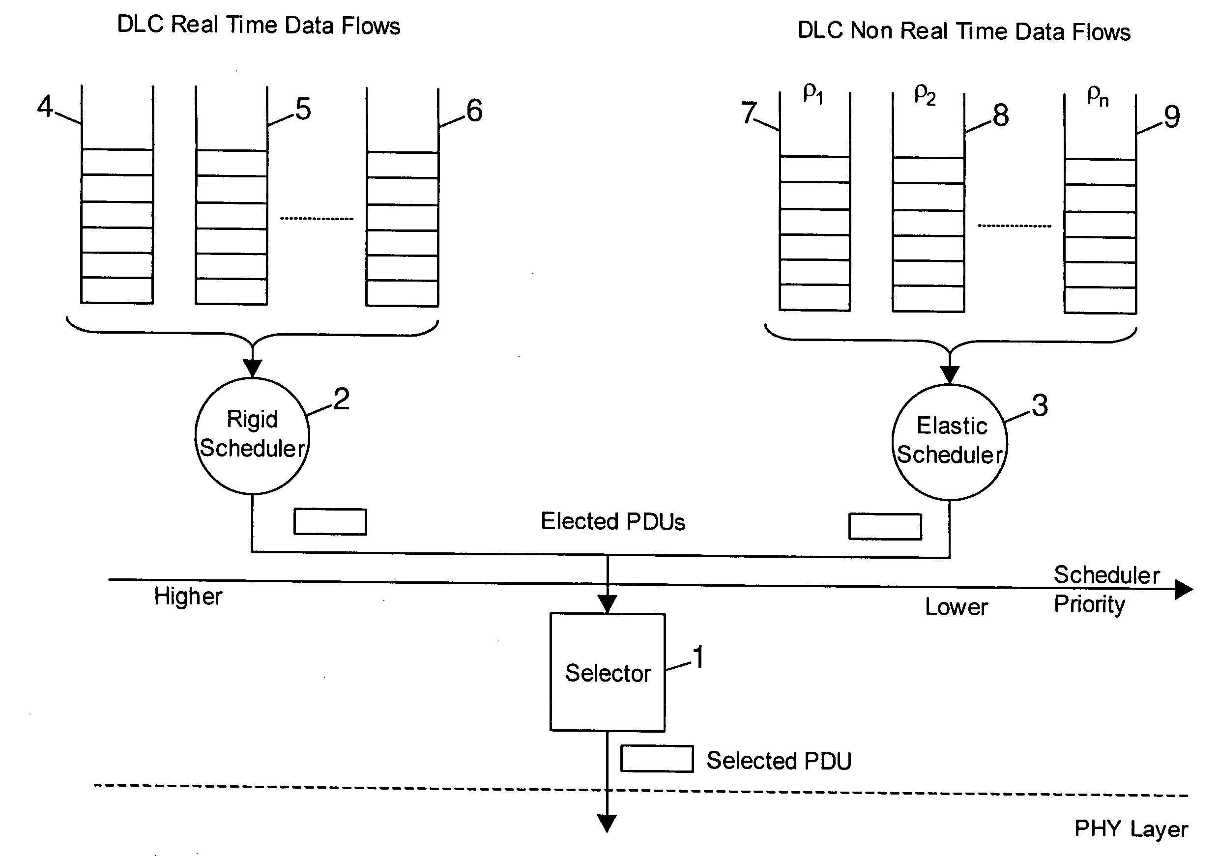
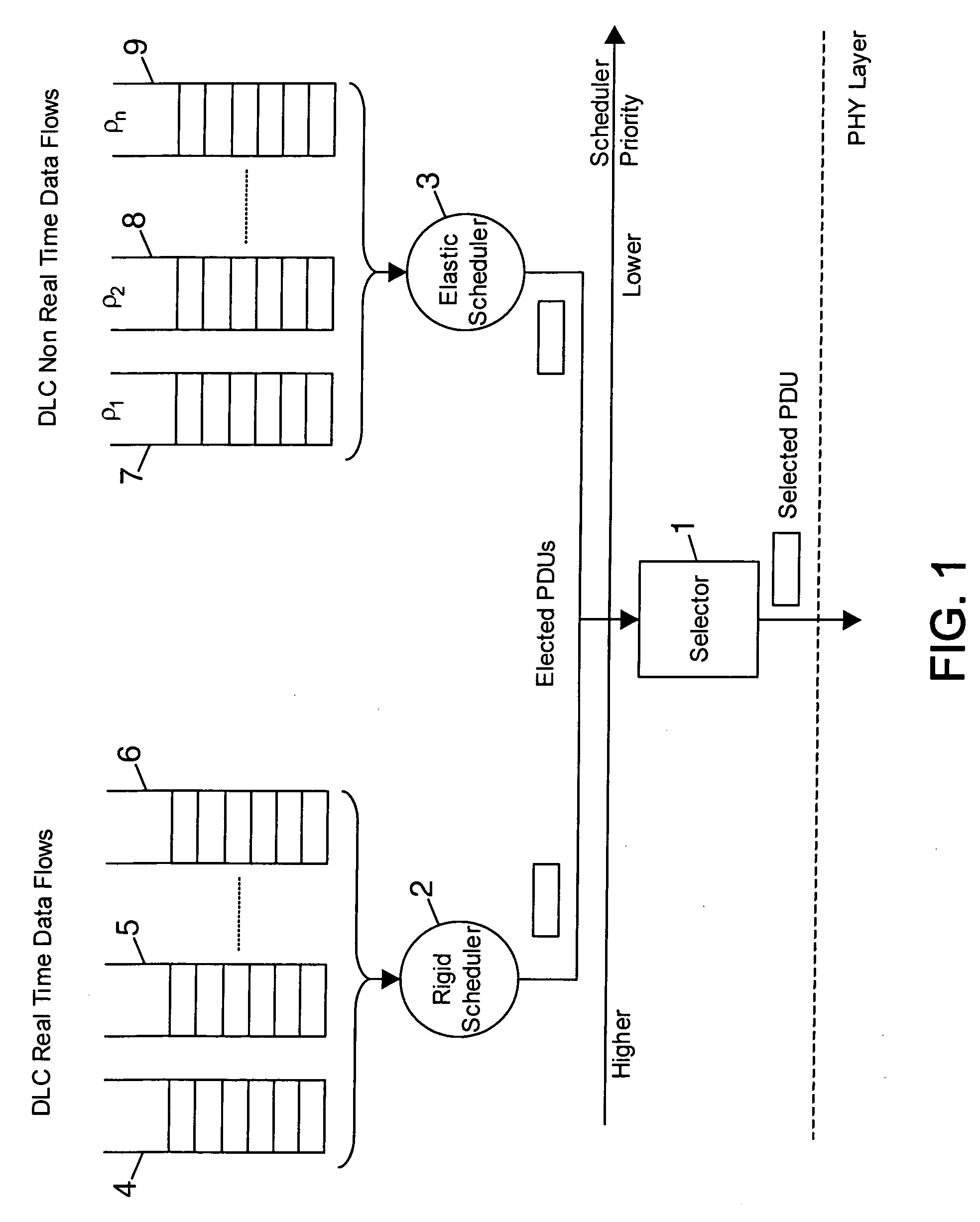
[0039] The present invention proposes a dynamic transmission resource allocation based on a plurality of scheduling schemes carrying out their respective rules independently each other.

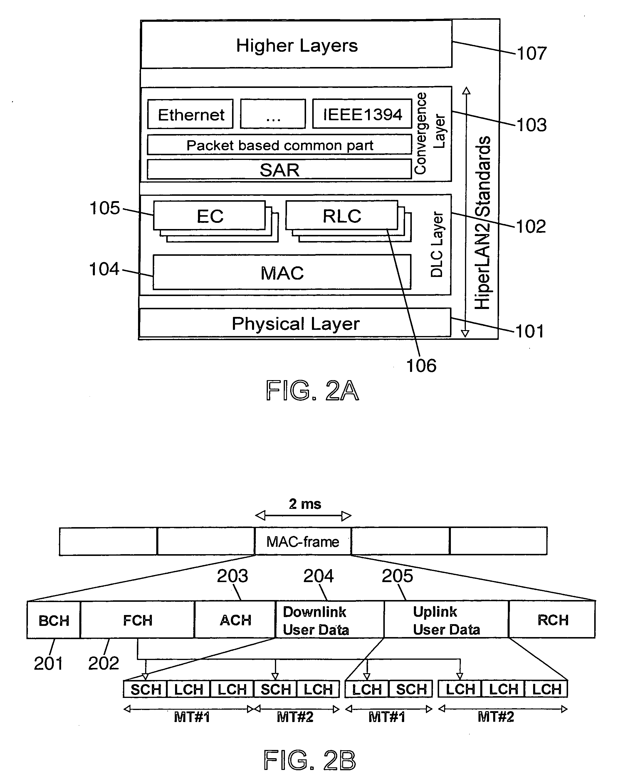
[0040] One exemplary embodiment of the present invention takes place in a wireless network comprising Mobile Terminals or MTs including a communication protocols stack based on the HiperLAN / 2 or HLAN / 2 or H / 2 standard defined by the European Telecommunication Standard Institute or ETSI. The transmission resource in the wireless network is shared among all MTs of this network, by the RRM unit. This RRM unit is in charge of centralising the allocation of the transmission resource in the network. Preferably, the transmission resource allocation is based on a TDMA scheme. Of course the scope of the invention encompasses applications to any stack of communication protocol layers, as well as applications to other types of networks and to a transmission resource allocation which is not based on TDMA scheme....


PUM


Abstract

There is disclosed a method of dynamic transmission resource allocation in a wireless network comprising a plurality of Mobile Terminals or MTs each managing a given number of different data flows (4-9) of Protocol Data Units or PDUs which are classified according to a set of flow types, a Radio Resource Management or RRM unit for allocating transmission resources on a per PDU basis; a plurality of schedulers (2,3) operating according to a specific set of rules; and a selector (1) for sharing the transmission resource among the MTs. The MTs or the RRM unit send Request Resource or RR messages to the RRM unit to request transmission resource. The RRM unit dispatches the RR messages to the schedulers based on flow type information included in each RR message. Each one of the schedulers elects one PDU as candidate for a next transmission resource allocation. The selector (1) allocates transmission resource to one candidate according to a set of priority rules, a given priority being assigned to each flow type. The specific set of rules comprises a rule applied in case of transmission errors for reducing the bandwidth allocated to data flows belonging to the flow types assigned with comparatively lower priority compared to the bandwidth allocated thereto according to a rule applied in case of error free transmission.

Description

BACKGROUND OF THE INVENTION [0001] 1. Technical Field [0002] The present invention relates generally to communication networks, and more particularly to the dynamic resource allocation in a network based on a centralised transmission resource allocation. [0003] 2. Related Art [0004] Wireless Local Area Networks (WLANs) have recently experienced a rapid development mainly due to the increase of the bandwidth they can offer. Concurrently, the number of users and the diversity of applications have grown. As a consequence, a WLAN simultaneously transports a large number of data flows generated by several types of applications. It results there from that the transmission resource which remains relatively scarce, requires a very efficient allocation mechanism. On the other hand, such a type of network as a wireless network provides a transmission resource not very reliable due to the radio medium. It results from it that some transmission errors can occur on one or several data flows. [00...

Claims


Application Information

Patent Timeline
Patent Type & Authority Applications(United States)
IPC IPC(8): H04L12/28H04L12/56H04L29/06H04W28/04H04W28/22H04W72/10H04J3/00H04W72/12H04W84/12
CPCH04W28/04H04W28/22H04L69/165H04W84/12H04L69/16H04W72/10H04W72/56
Inventor MANGIN, CHRISTOPHEROLLET, ROMAIN
Owner MITSUBISHI ELECTRIC CORP
Why Eureka
Try Eureka