System and method for detecting link failures

a technology of link failure and detection system, applied in the field of computer networks, can solve the problems of failure detection packet interruption, carrier drop, failure detection engine concludes that the point-to-point link has failed, etc., and achieve the effect of rapid and efficient detection of failures

Active Publication Date: 2005-11-10
CISCO TECH INC
View PDF35 Cites 151 Cited by
  • Summary
  • Abstract
  • Description
  • Claims
  • Application Information

AI Technical Summary

Benefits of technology

[0018] Briefly, the present invention is directed to a system and method for monitoring operation of links in a computer network and for rapidly and efficiently detecting failures of those links. In an illustrative embodiment, the computer network includes a plurality of intermediate network devices, including two network devices, such as bridges, that are interconnected by a point-to-point link having a carrier that supports a data-bearing signal. Each bridge has a link establishment entity and is further configured to include a failure detection engine that is in communication with the respective bridge port coupled to the point-to-point link. The failure detection engine includes a message generator, one or more state machines and fast failure detector logic. In the illustrative embodiment, the state machine transitions selected ports among the enabling, working, disabling and failed states.

Problems solved by technology

If a break in communication, i.e., an interruption in the receipt of network messages and / or failure detection packets is detected, then the failure detection engine concludes that the point-to-point link has failed.
The failure detection engine subsequently causes the carrier to be dropped and the link to be shut-down.
The receiving bridge does not, however, conclude that the interruption in failure detection packets is a result of a failure of the link.

Method used


Image

  • System and method for detecting link failures
  • System and method for detecting link failures
  • System and method for detecting link failures

Examples


Embodiment Construction

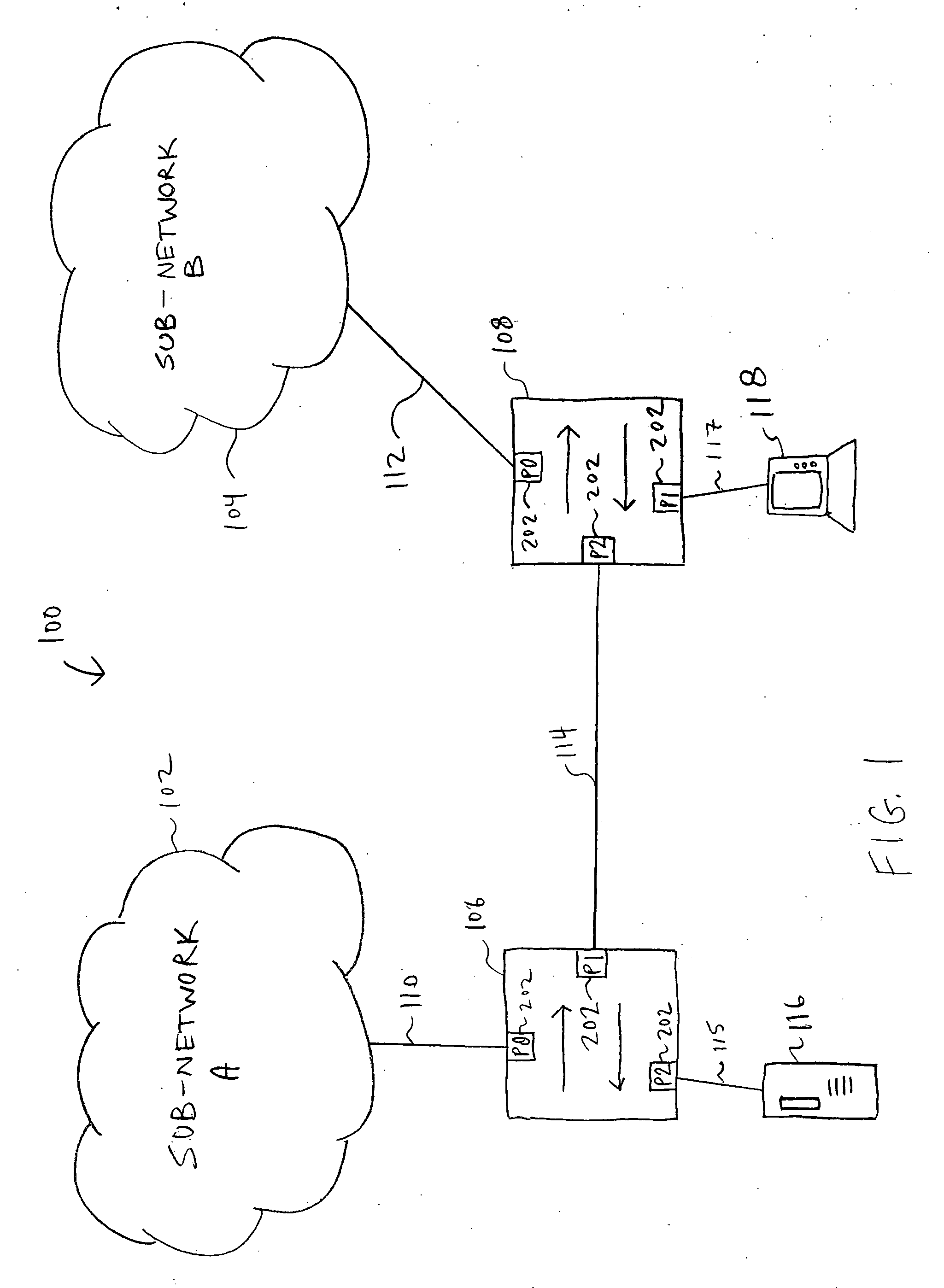
[0030]FIG. 1 is a highly schematic illustration of a computer network 100 that includes two sub-networks, e.g., sub-network A 102 and sub-network B 104. Computer network 100 further includes a plurality of, e.g., two, intermediate network devices 106, 108. Network device 106 is coupled by link 110 to sub-network 102, and network device 108 is coupled by link 112 to sub-network 104. In addition, the two network devices 106, 108 are interconnected by a point-to-point link 114. Coupled to each network device 106, 108 may be one or more local area networks (LANs) and / or end stations. For example, a server 116 is coupled to network device 106 via link 115, while a workstation or personal computer 118 is coupled to network device 108 via link 117. The two sub-networks 102, 104 preferably include a plurality of interconnected LANs, end stations and intermediate network devices (not shown).

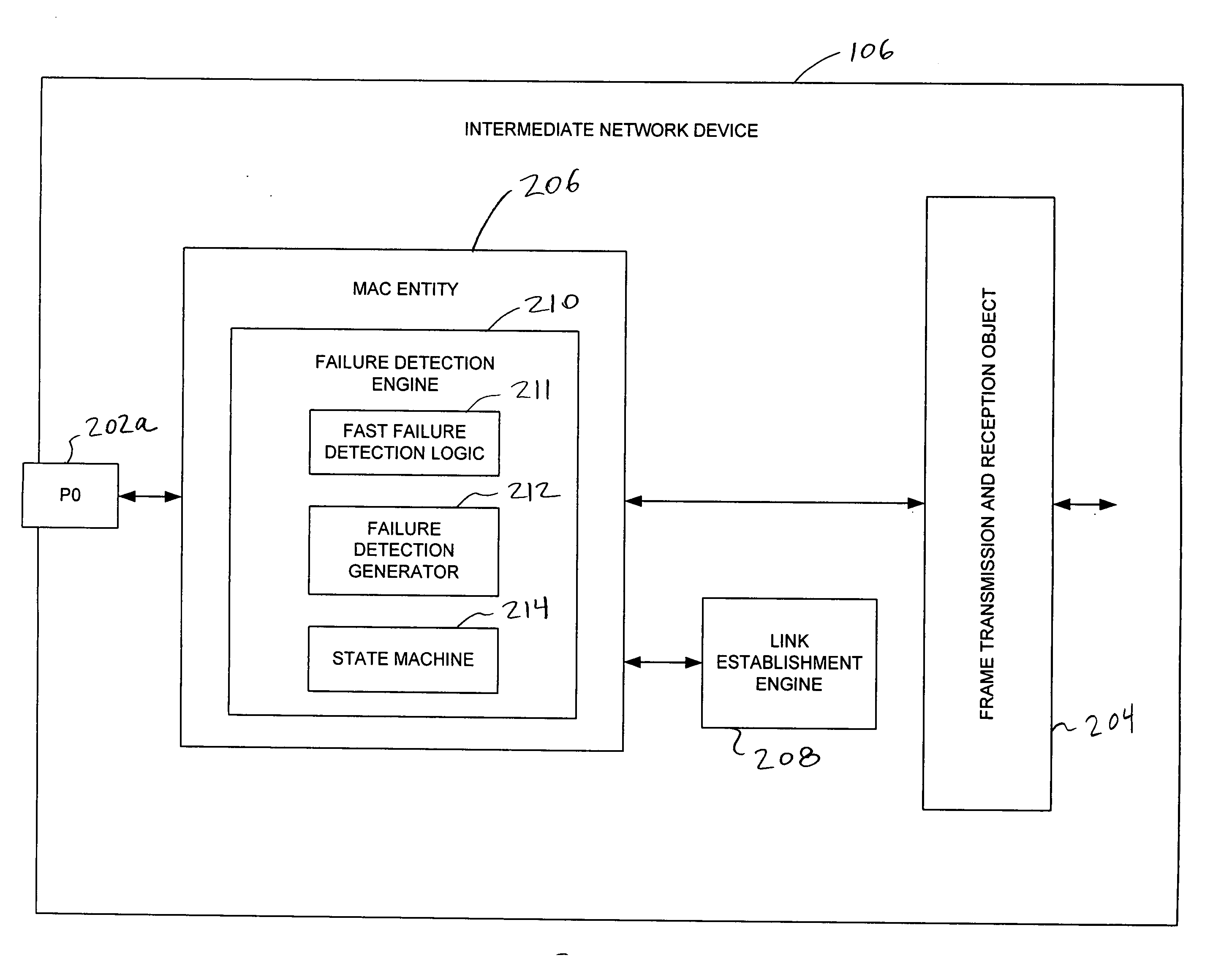
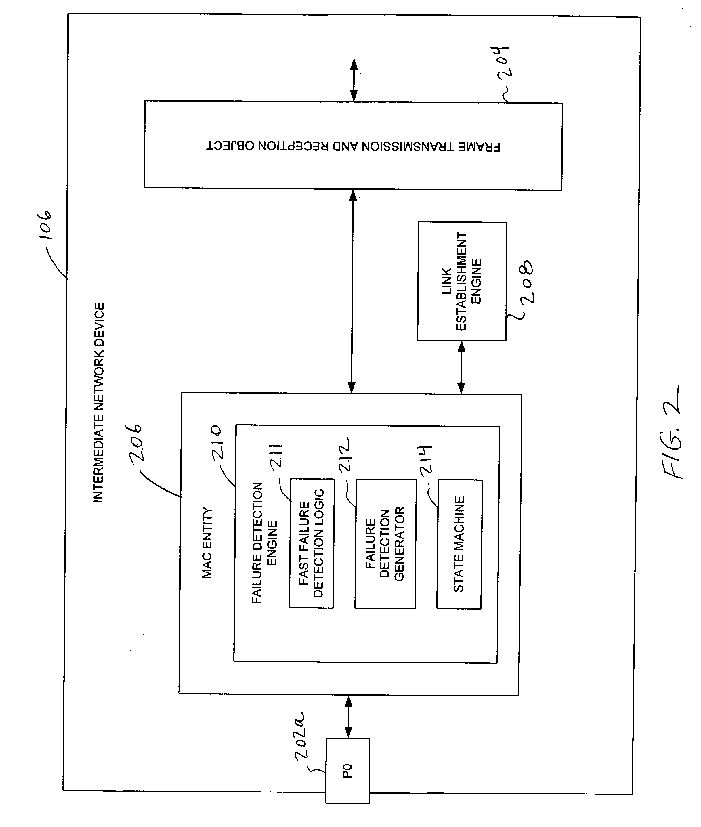
[0031] Each network device 106, 108 has a plurality of ports 202, and is configured to switch or forw...


PUM


Abstract

A system and method monitors links in a computer network and rapidly detects failures of such links. Network entities disposed at opposite ends of a link are provided with failure detection engines that signal their presence to each other. Thereafter, each failure detection engine ensures that its entity transmits a continuous stream to the other entity by sending either data frames or newly defined failure detection packets. If an interruption in this continuous stream is detected, then the failure detection engine concludes that the link has failed. In response, the failure detection engine preferably notifies other applications or protocols of the failure, and causes the link to be shut-down.

Description

BACKGROUND OF THE INVENTION [0001] 1. Field of the Invention [0002] The present invention relates generally to computer networks, and more specifically, to a method and apparatus for quickly and efficiently detecting link failures. [0003] 2. Background Information [0004] Many organizations, including businesses, governments and educational institutions, utilize computer networks so that employees and others may share and exchange information and / or resources. A computer network typically comprises a plurality of entities interconnected by means of one or more communications media. An entity may consist of any device, such as a computer, that “sources” (i.e., transmits) or “sinks” (i.e., receives) messages, such as data frames, over the communications media. A common type of computer network is a local area network (“LAN”) which typically refers to a privately owned network within a single building or campus. LANs typically employ a data communication protocol (LAN standard), such as...

Claims


Application Information

Patent Timeline
Patent Type & Authority Applications(United States)
IPC IPC(8): H04L12/24H04L12/26H04L12/28
CPCH04L12/2697H04L41/0677H04L43/50H04L43/10H04L43/0811
Inventor FINN, NORMAN W.
Owner CISCO TECH INC
Why Eureka
Try Eureka