
Method and apparatus for preventing dock or structure piling uplift

a technology for docks and structures, applied in the field of docks and structural pilings, can solve the problems of pilings being lifted, water around the piling freezes, and defeat the purpose of prior art devices, and achieve the effect of preventing piling upli

Inactive Publication Date: 2005-11-10
COLBERT ROBERT
View PDF3 Cites 0 Cited by
  • Summary
  • Abstract
  • Description
  • Claims
  • Application Information

AI Technical Summary

Benefits of technology

[0011] It is therefore an aspect of the present invention to overcome the shortfalls of the prior art and provide a method and apparatus that prevents piling uplift in extreme cold weather environments.
[0012] It is a further aspect of the invention to provide a method and apparatus for preventing piling uplift by preventing the water between the device and the piling from freezing.
[0016] In accordance with another aspect of the invention, the support device includes a flat pipe having an elongate cavity and end seals for providing a water and air tight seal. The heat trace cable is disposed in elongate cavity and is connected to the electric connection through said flat pipe or said end seals. The air chamber in the flat pipe will help the flotation of the device around a piling.
[0019] According to a further aspect of the invention, the support device can be formed of a first tubular member for receiving the heat trace cable, and a second tubular member for receiving the first tubular member such that an air chamber is formed between the first and second tubular members. An end cap on each end encloses the open ends in a water and air tight manner and create an air chamber between the two tubular members. The air chamber facilitates the flotation of the device.

Problems solved by technology

However, with the increasingly colder winters in, the temperatures are so low below freezing that the water around the piling freezes.
This freezing of the water adjacent the piling defeats the purpose of the prior art devices and causes the piling to lift, along with prior art piling anti-lift devices.

Method used


Image

  • Method and apparatus for preventing dock or structure piling uplift
  • Method and apparatus for preventing dock or structure piling uplift
  • Method and apparatus for preventing dock or structure piling uplift

Examples


Embodiment Construction

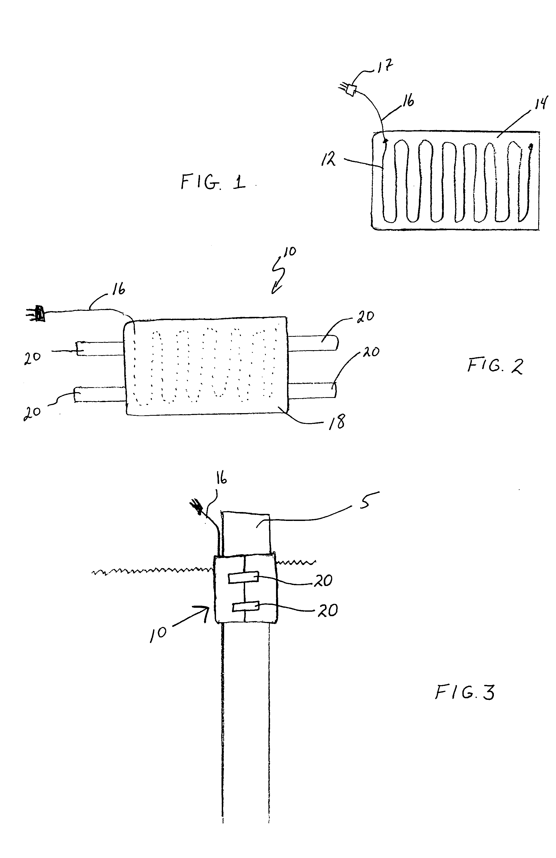
[0032]FIGS. 1-3 show the piling anti-lift system 10 according to an aspect of the invention. As shown, a heat trace cable 12 is connected to a flat sheet 14 in any suitable configuration. Flat sheet 14 is preferably a plastic or rubberized sheet capable of withstanding cold temperatures in the range of 20-40 degrees Fahrenheit. The electric connection 16 is connected to the heat trace cable 12 and includes a plug end 17 for connection to an outlet.

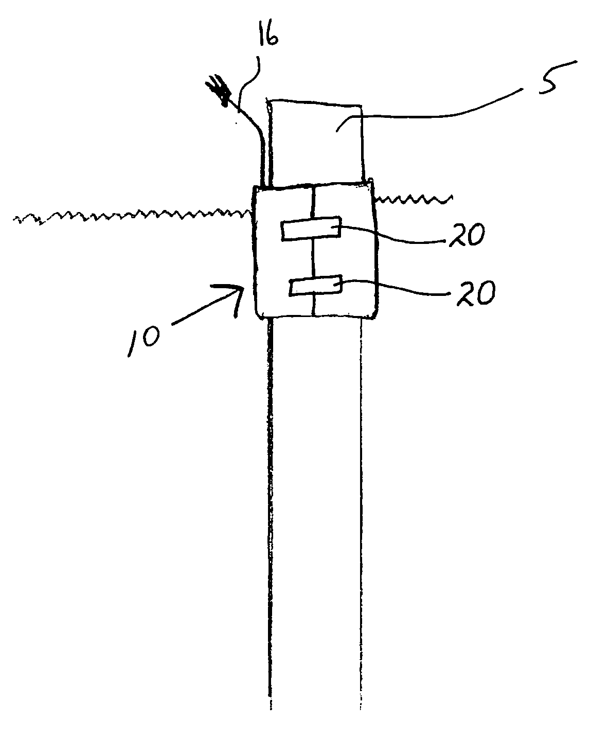
[0033] The flat sheet 14 with heat trace cable adhered thereto is then enclosed in a waterproof material 18 (e.g., fabric, plastic, etc.) and releasably connectable straps 20 are provided on each end of the enclosed sheet 14. The anti-piling list system 10 can then be wrapped around a piling 5 (FIG. 3) and function to prevent the same from being lifted due to freezing water or terrain.

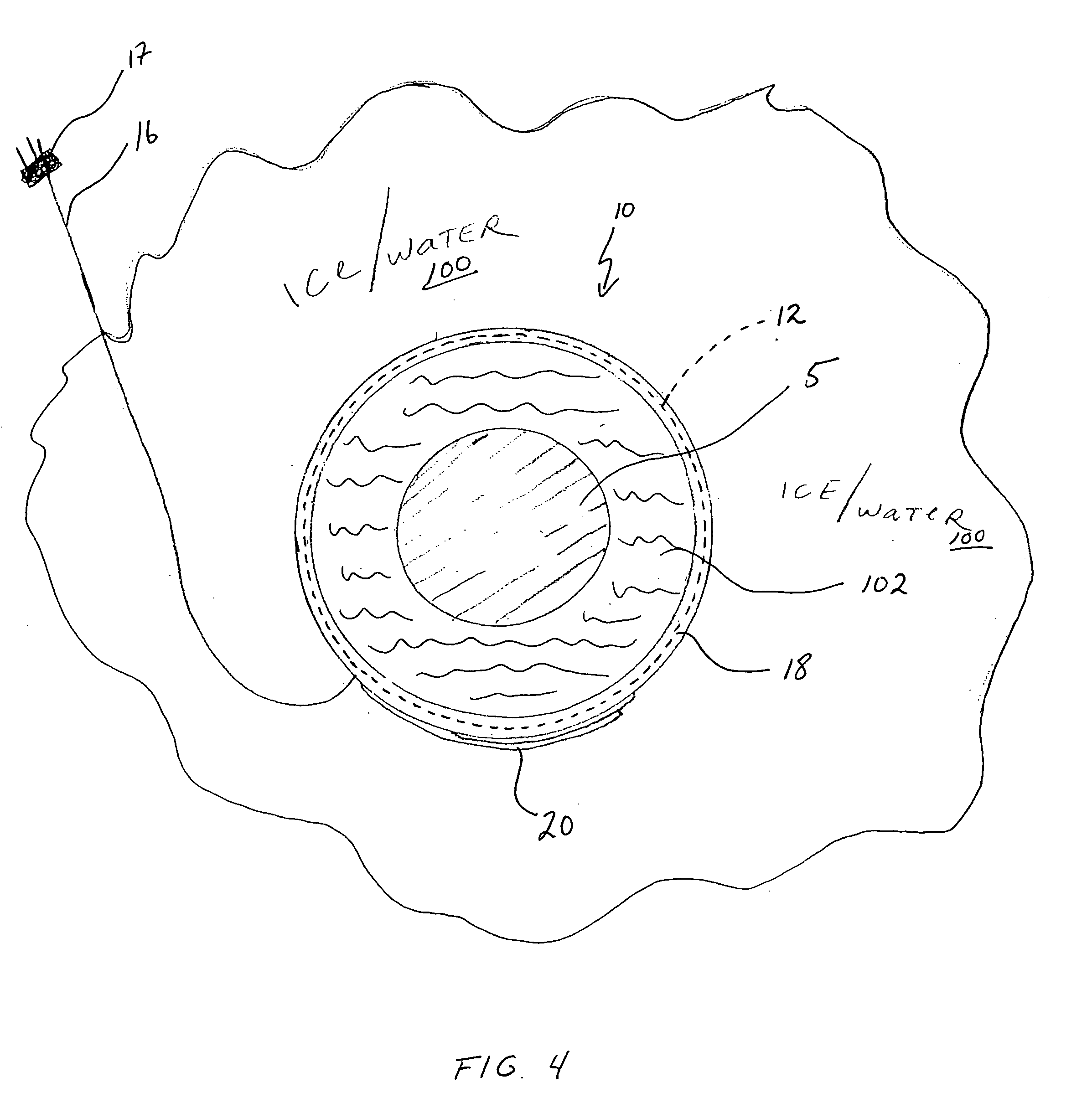
[0034]FIG. 4 shows the concept of the present invention as applied with the piling anti-lift system 10. It is important to understand that this concept app...


PUM


Abstract

A piling anti-lift system utilizes a heat trace cable secured around a piling and extending above and below the water level of the surrounding water. An annular space is formed between the piling anti-lift system. The heated piling anti-lift system prevents the water in the annular space from freezing and thereby prevents the piling from being subject to uplifting or heaving that results from the rising tide of surrounding frozen waters. In the event of extreme water temperatures and the freezing of the water in the formed annular space, the piling anti-lift system keeps the piling independent of the frozen surrounding water. In this situation, the piling anti-lift system will break free from the frozen water in the annular area and rise with the rising tide waters, thus continuing to keep the piling independent from the rising frozen tide waters.

Description

RELATED APPLICATION INFORMATION [0001] This application is a Continuation-in-Part of co-pending U.S. patent application Ser. No. 10 / 842,590 filed May 10, 2004, the entire contents of which are incorporated herein by reference.BACKGROUND OF THE INVENTION [0002] 1. Field of the Invention [0003] The present invention relates to dock and structural pilings. More particularly, it relates to a method and apparatus for preventing piling uplift caused by frost heaving or shifting, or rising frozen tide waters. [0004] 2. Description of the Prior Art [0005] U.S. Pat. No. 4,127,002 relates to a permanent pier piling for use in docks and the like in a body of water whereby an antifreeze solution within the piling circulates to distribute latent ground heat from the lower portion of the piling to the upper portion of the piling to maintain a fluid interface between the piling and the ice during the winter season. [0006] U.S. Pat. No. 4,464,083 relating to an ice guard for protecting a vertically...

Claims


Application Information

Patent Timeline
IPC IPC(8): E02D5/60E02D31/06E02D31/12E02D31/14
CPCE02D31/14E02D31/12
Inventor COLBERT, ROBERT
Owner COLBERT ROBERT
Learn More