Bone conductive speaker

a bone conductive speaker and speaker body technology, applied in the direction of transducer details, mechanical vibration separation, electrical transducers, etc., can solve the problems of reduced size, inability to meet the demand for much more downsizing of the speaker, and difficulty in producing a slim or thin-thickness type of magnet having a sufficient physical strength

Inactive Publication Date: 2005-11-17
TEMCO JAPAN
View PDF7 Cites 8 Cited by
  • Summary
  • Abstract
  • Description
  • Claims
  • Application Information

AI Technical Summary

Problems solved by technology

This makes it inevitably necessary to increase the bone conductive speaker in outer diameter.
In the outer magnet type of conventional bone conductive speaker, however, since its magnet is disposed in the outer peripheral portion of the speaker, and also since it is difficult to produce the magnet of a slim or thin-thickness type having a sufficient physical strength at a low cost, it is necessary for the outer magnet type of bone conductive speaker to prevent its magnet from being too reduced in size.
Due to this, it is not possible for the conventional bone conductive speaker to sufficiently meet the demand for much more downsizing of the speaker.
Consequently, also in this inner magnet type of bone conductive speaker, it is not possible to meet the demand for much more downsizing of the speaker.
As described above, any type of the conventional bone conductive speaker fails to meet the demand for much more downsizing of the speaker in incorporating the bone conductive speaker into a cellular phone.

Method used


Image

  • Bone conductive speaker
  • Bone conductive speaker
  • Bone conductive speaker

Examples


Embodiment Construction

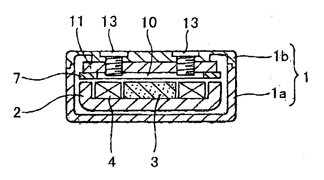
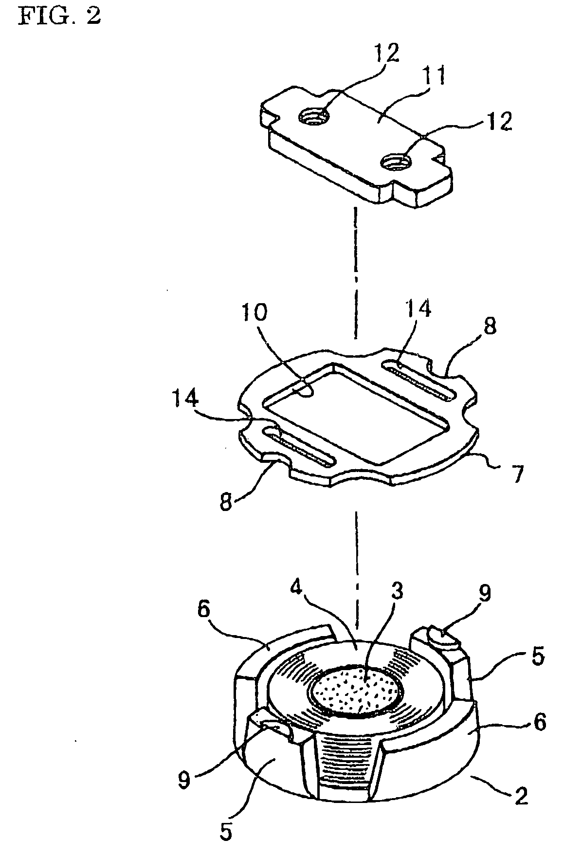
[0018] With reference to the accompanying drawings, embodiments of the present invention will be described. FIG. 1 is a longitudinal sectional view of the bone conductive speaker of the present invention, illustrating the entire construction of the speaker comprising a housing 1. FIG. 2 is an exploded perspective view of the bone conductive speaker of the present invention, illustrating a vibrating portion and a drive portion of the speaker both received in the housing 1. FIG. 3 is a perspective view of an assembly, wherein the assembly is assembled from both the vibrating portion and the drive portion of the bone conductive speaker of the present invention.

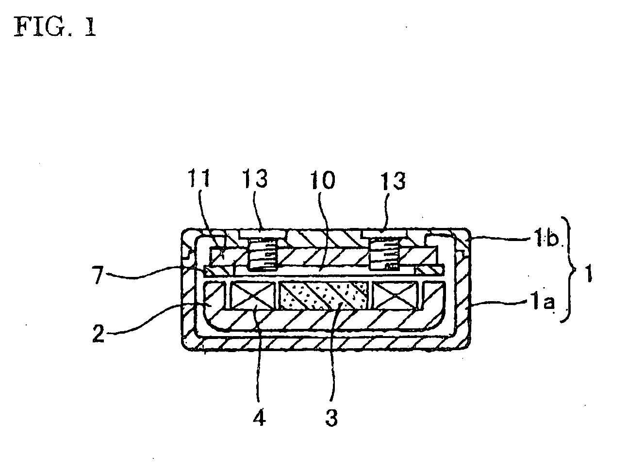
[0019] As shown in FIG. 1, the housing 1 is divided into: an upper portion which is formed into a lid portion 1b; and, a lower portion which is formed into a container portion 1a in which the drive portion is received in a floating manner. The lid portion 1b of the housing 1 is fixedly mounted on the drive portion thereof.

[0020...


PUM


Abstract

A bone conductive speaker is downsized without causing any loss in efficiency, simple in construction low in cost, and comprises yoke (2), magnet (3) disposed in a central area of the yoke, and voice coil (4) wound on the magnet. The yoke has its peripheral area divided into a plurality of upright portions; of the upright portions, each of first ones (5) oppositely disposed from each other is provided with a first engaging means (9) in its upper surface; second engaging means (8) each corresponding to the first engaging means are provided in a vibrating plate (7). The vibrating plate is mounted on a lid portion of the housing in a manner such that the vibrating plate is disposed on the upright portions of the yoke and fixedly mounted by means of the second engaging means in a manner such that the vibrating plate floats in the housing.

Description

FIELD OF THE INVENTION [0001] The present invention relates to a bone conductive speaker, and more particularly to a bone conductive speaker of a type adapted to be held in abutting contact with a head portion of a user for transmitting a vibration of a diaphragm or vibrating plate of the bone conductive speaker to a bone tissues of the head portion of the user, which makes it possible for the user to catch the sound. BACKGROUND OF THE INVENTION [0002] A conventional bone conductive speaker has a known construction such as one shown in FIGS. 4(A) and 4(B). Such bone conductive speaker is constructed of: a cylindrical casing 21 provided with a diaphragm or vibrating plate 22 in its upper surface; a magnet 23 mounted in the casing 21 in an insertion manner; a yoke 25, which is mounted in a lower portion of the casing in an insertion manner and provided with a center magnet pole 24 in its central area; and, a voice coil 26, with which the center magnet pole 24 of the yoke 25 is encircl...

Claims


Application Information

Patent Timeline
Patent Type & Authority Applications(United States)
IPC IPC(8): H04R1/00B06B1/04H04R9/10H04R13/00
CPCH04R9/10H04R13/00H04R2499/11H04R2460/13H04R2400/03H04R1/00
Inventor KOBAYASHI, KAZUJI
Owner TEMCO JAPAN
Why Eureka
Try Eureka