
Star flexible coupling

a flexible coupling and coupling technology, applied in the direction of yielding couplings, couplings, mechanical devices, etc., can solve the problem of severe limit the shaft misalignment/offset possibl

Inactive Publication Date: 2005-11-17
PIASECKI FR N +2
View PDF2 Cites 14 Cited by
  • Summary
  • Abstract
  • Description
  • Claims
  • Application Information

AI Technical Summary

Problems solved by technology

However, one disadvantage of such known arrangements is that they severely limit the shaft misalignment / offset possible.

Method used


Image

  • Star flexible coupling
  • Star flexible coupling
  • Star flexible coupling

Examples


Embodiment Construction

[0010] Embodiments of the present invention overcome several of the disadvantages of known couplings. The embodiments relate to a flexible coupling for connecting a driving rotatable shaft to a driven rotatable shaft, where the flexible coupling allows greater relative misalignment and / or offset of the shafts compared to known couplings. The coupling may further enable control of torsional and axial stiffness.

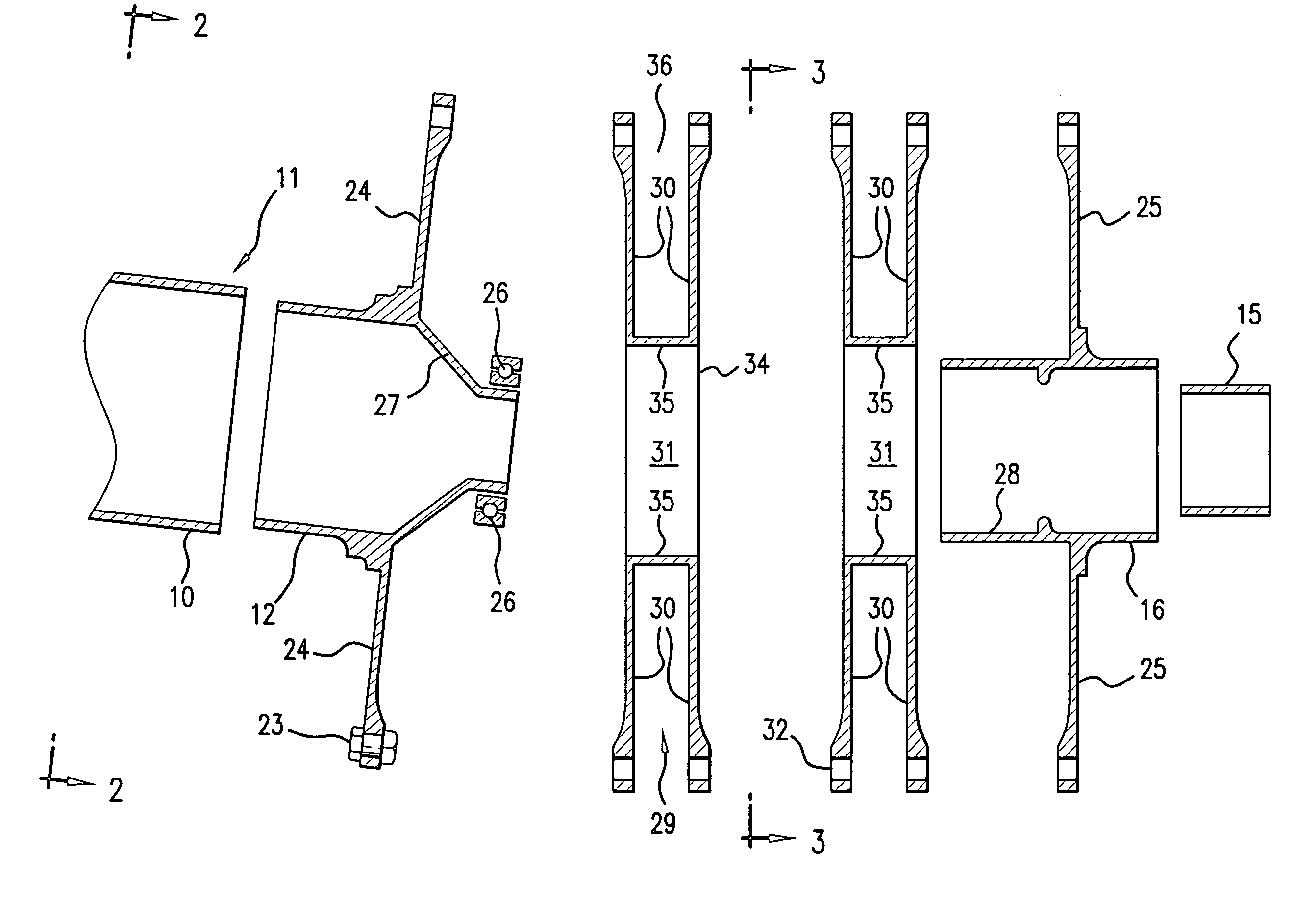
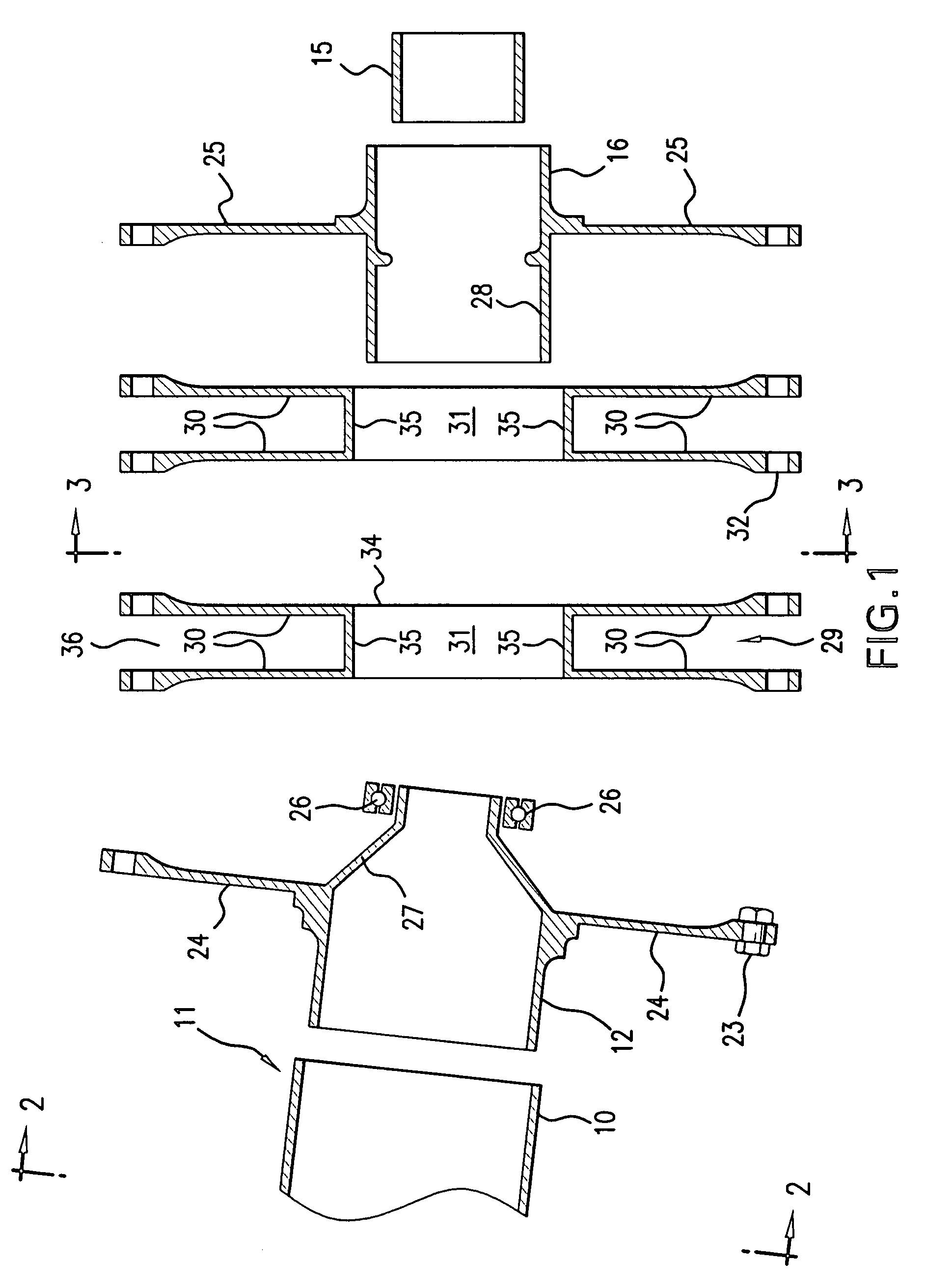
[0011]FIG. 1 shows an exploded view of a cross section of a flexible coupling 100 according to embodiments of the present invention. FIG. 4 shows the same cross section of the flexible coupling 100 of FIG. 1, where the coupling is in an assembled form.

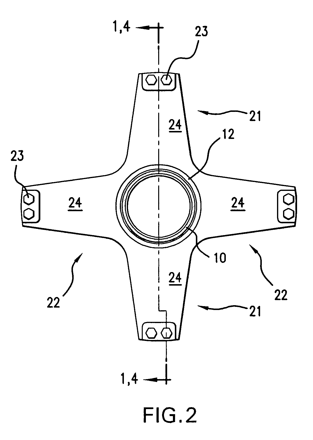
[0012] The coupling 100 may comprise a driving hub 12 adapted to be coupled to a rotatable driving shaft 11. For example, the driving hub 12 could be received within, bolted to or otherwise fastened to an end 10 of the rotatable driving shaft 11. The driving hub 12 may have a plurality of arms 24.

[0013] A driven hub 16 may be a...


PUM


Abstract

Embodiments of the present invention relate to a flexible coupling for connecting a driving rotatable shaft to a driven rotatable shaft, where the flexible coupling allows greater relative misalignment and / or offset of the shafts compared to known couplings. The coupling may further enable control of torsional and axial stiffness.

Description

[0001] This application is a continuation-in-part of U.S. application Ser. No. 10 / 188,253, filed Jul. 3, 2002 and fully incorporated herein by reference.BACKGROUND OF THE INVENTION [0002] Mechanical couplings to transmit power from one shaft to another, where both shafts turn around the same nominal centerline, are known. Broadly speaking, types of known couplings include fixed-type and flexible-type couplings. [0003] Flexible-type couplings may be particularly appropriate for use with shafts that have some angular misalignment relative to each other, have a small parallel offset relative to each other, or have both an angular misalignment and parallel offset relative to each other. More specifically, the misalignment and / or offset may exist with respect to respective theoretical centerlines of coupled shafts. [0004] Crown splines, flexible disks and diaphragm-type couplings are examples of known techniques for accommodating shaft misalignment and / or offset. However, one disadvantag...

Claims


Application Information

Patent Timeline
IPC IPC(8): F16D3/50F16D3/72
CPCF16D3/72F16D3/50
Inventor PIASECKI, FRANK N.PIASECKI, FREDERICK W.FOLENTA, DEZI J.
Owner PIASECKI FR N
Learn More