
Multiple instance spanning tree protocol

a tree protocol and instance technology, applied in the field of computer networks, can solve the problems of high undesirable loops, circuitous paths or loops within the network, and proliferation of data frames along loops

Active Publication Date: 2005-11-24
CISCO TECH INC
View PDF15 Cites 196 Cited by
  • Summary
  • Abstract
  • Description
  • Claims
  • Application Information

AI Technical Summary

Benefits of technology

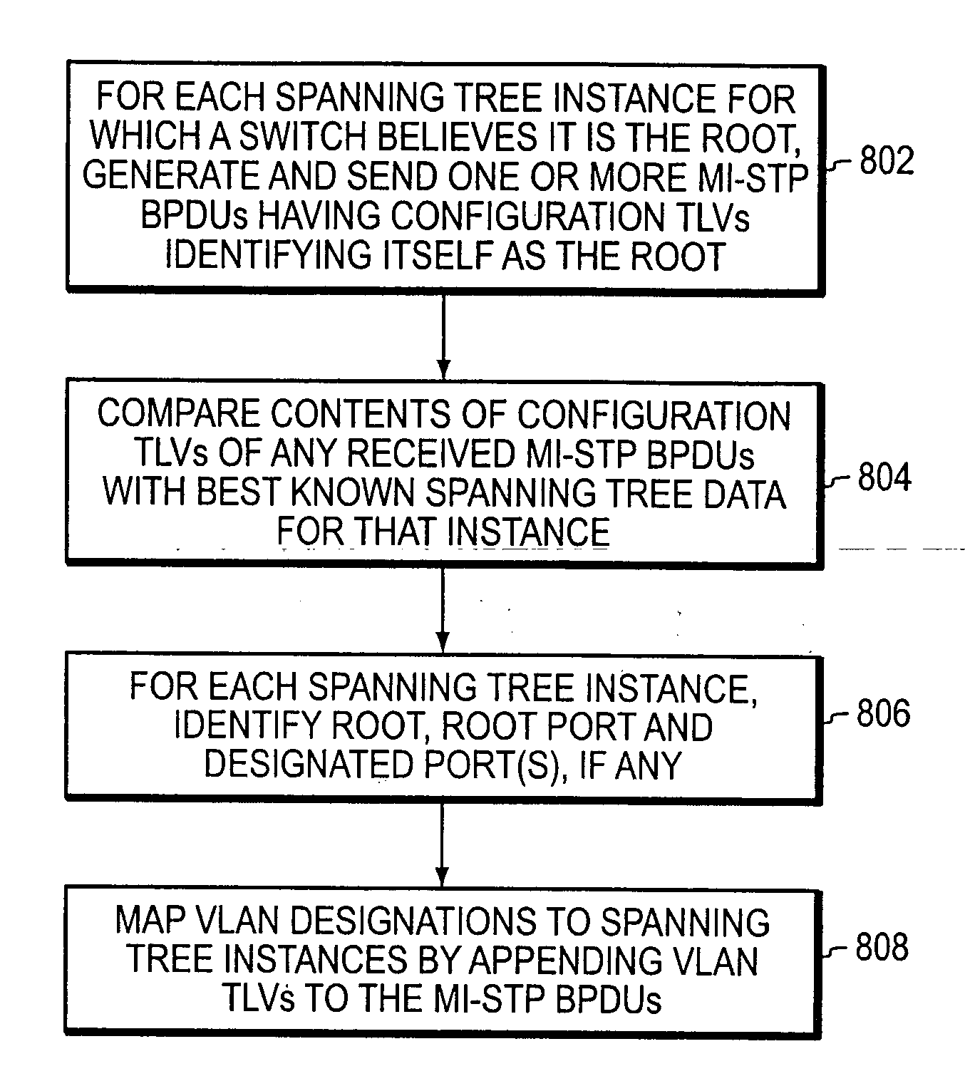
The invention is about a way to create multiple active topologies (loop-free paths) within a computer network using a protocol called multiple instance spanning tree (MI-STP). This is done by exchanging data between network devices using special messages. The MI-STP protocol allows for the creation of these active topologies regardless of any virtual local area network (VLAN) designations in the network. The MI-STP messages also contain information about which VLAN designations are mapped to which active topology for load balancing.

Problems solved by technology

The existence of redundant links, however, may cause the formation of circuitous paths or “loops” within the network.
Loops are highly undesirable because data frames may traverse the loops indefinitely.
Furthermore, some devices, such as bridges or switches, replicate frames whose destination is not known resulting in a proliferation of data frames along loops.
The resulting traffic effectively overwhelms the network.
For example, by defining a single spanning tree for a network having numerous VLAN designations, the IEEE solution does not allow for load balancing.
This may significantly degrade performance over certain, heavily utilized, portions of the network, limiting message throughput.
First, this approach may not scale well to large networks.
Depending on the number of VLAN designations within the network, this may severely tax the processing and memory resources of the switches, degrading network efficiency.

Method used


Image

  • Multiple instance spanning tree protocol
  • Multiple instance spanning tree protocol
  • Multiple instance spanning tree protocol

Examples


Embodiment Construction

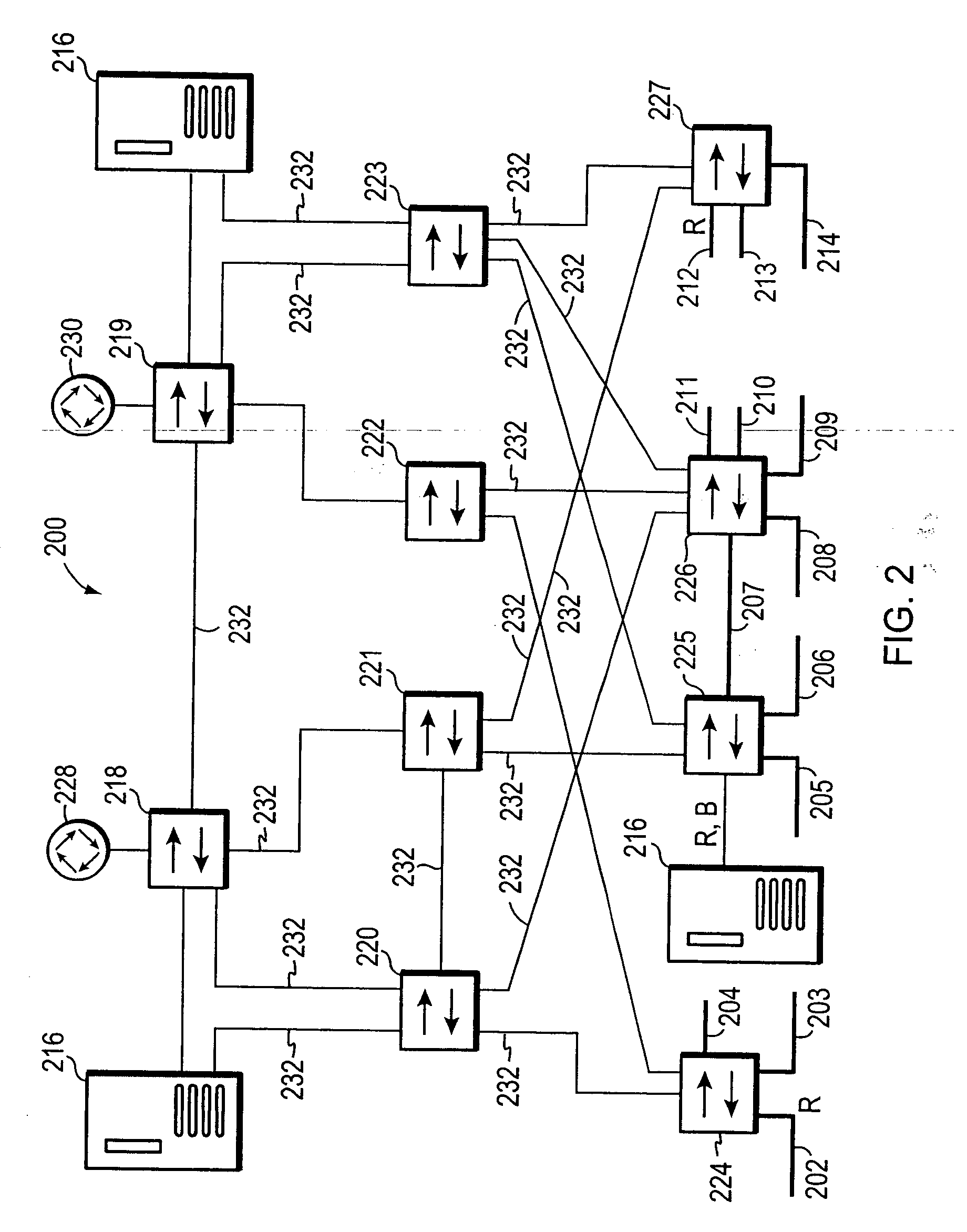
[0037]FIG. 2 illustrates a partially meshed computer network 200 in accordance with the present invention. The network 200 preferably comprises a plurality of local area networks (LANs) 202-214 and servers 216, such as file servers, print servers, etc., interconnected by a plurality of intermediate devices, such as switches 218-227. One or more entities or hosts (not shown) are preferably coupled to each LAN 202-214 so that the entities may source or sink data frames to one another or to the servers 216 over the network 200. Each switch 218-227, moreover, preferably includes a plurality of ports such that each LAN 202-214 and server 216 is coupled to at least one port of switches 218-227.

[0038] The network 200 may further include one or more routers 228, 230. Switches 218-227 and routers 228, 230 are preferably interconnected by a series of links 232, such as point-to-point links. Links 232 carry messages, such as data frames, between switches 218-227 and routers 228, 230. Each swi...


PUM


Abstract

A multiple instance spanning tree protocol (MI-STP) creates a plurality of active topologies (i.e., loop-free paths) within a computer network. These active topologies may be established through the exchange and processing of multiple instance spanning tree bridge protocol data unit messages (MI-STP BPDUs) by the intermediate network devices within the network. The active topologies are preferably created independently of any virtual local area network (VLAN) designations defined within the network. Once the active topologies are defined, each VLAN designation is then mapped to a single active topology, although multiple VLAN designations are preferably mapped to the same active topology to provide load balancing.

Description

CROSS-REFERENCE TO RELATED APPLICATIONS [0001] This application is related to the following co-pending, commonly owned U.S. Patent Applications: [0002] U.S. patent application Ser. No. 08 / 997,297 entitled SHARED SPANNING TREE PROTOCOL, filed Dec. 23, 1997; and [0003] U.S. patent application Ser. No. 09 / 283,111 entitled METHOD AND APPARATUS FOR PROVIDING FAST SPANNING TREE RE-STARTS, filed Mar. 31, 1999.BACKGROUND OF THE INVENTION [0004] 1. Field of the Invention [0005] The present invention relates generally to computer networks and, more specifically, to a protocol for defining multiple instances of loop-free paths within a computer network. [0006] 2. Background Information [0007] Many organizations, including businesses, governments and educational institutions, utilize computer networks so that employees and others may share and exchange information and / or resources. A computer network typically comprises a plurality of entities interconnected by means of one or more communicatio...

Claims


Application Information

Patent Timeline
Patent Type & Authority Applications(United States)
IPC IPC(8): H04L12/28H04L12/46H04L12/56
CPCH04L12/462H04L12/4641H04L45/48H04L12/4695H04L45/02H04L12/4691
Inventor BENEDETTO, MARCO DIMELLACHERUVU, RAMANAFINN, NORMAN W.MAHAJAN, UMESH
Owner CISCO TECH INC
Learn More