Clasp assembly for a watch chain

a technology of clasp assembly and watch chain, which is applied in the direction of bracelets, wristwatch straps, apparel, etc., can solve the problems of inconvenient use and assembly of conventional watch chains, complicated structure of clasp assembly of metallic watch chains, and high cost, so as to improve the security of use

Inactive Publication Date: 2005-12-01
JOLLY HOPE ENTERPRISE
View PDF8 Cites 17 Cited by
  • Summary
  • Abstract
  • Description
  • Claims
  • Application Information

AI Technical Summary

Benefits of technology

[0018] The problems existing in the prior art are solved by adding a pair of hook clasp and locking clasp, which can be assembled and disassembled manually, to the connection of the conventional watch chain and the clasp to form a clasp assembly, which can be connected and disconnected with the watch chain quickly.
[0019] The clasp assembly further has a security cover to improve the security of use and effectively prevent the clasp assembly from being unlocked accidentally, which may lead to losing the watch.

Problems solved by technology

In the prior art, the structure of a clasp assembly for a metallic watch chain is very complicated, involves a lot of parts, and is difficult to assemble and maintain.
Since tools must be used, it is inconvenient to use and assemble the conventional watch chains and clasps sold in the market or disclosed in Chinese Patent No. 99200269.9.

Method used


Image

  • Clasp assembly for a watch chain
  • Clasp assembly for a watch chain
  • Clasp assembly for a watch chain

Examples


Embodiment Construction

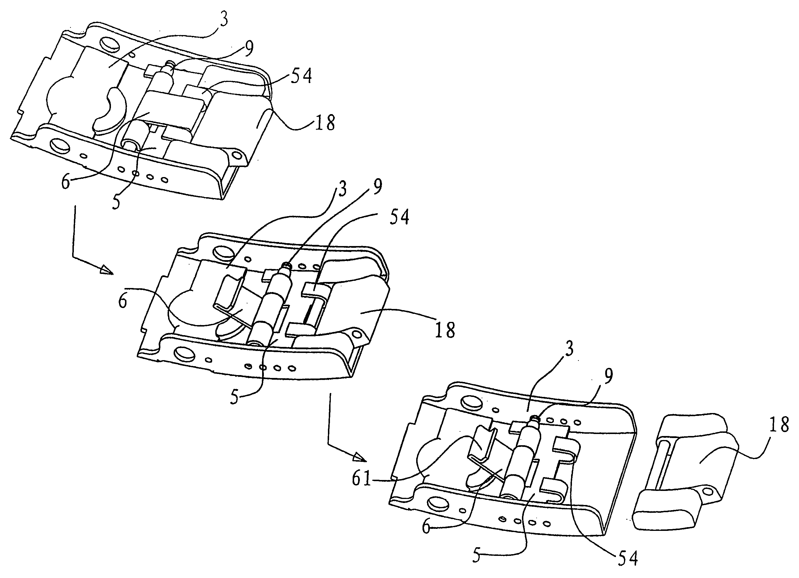
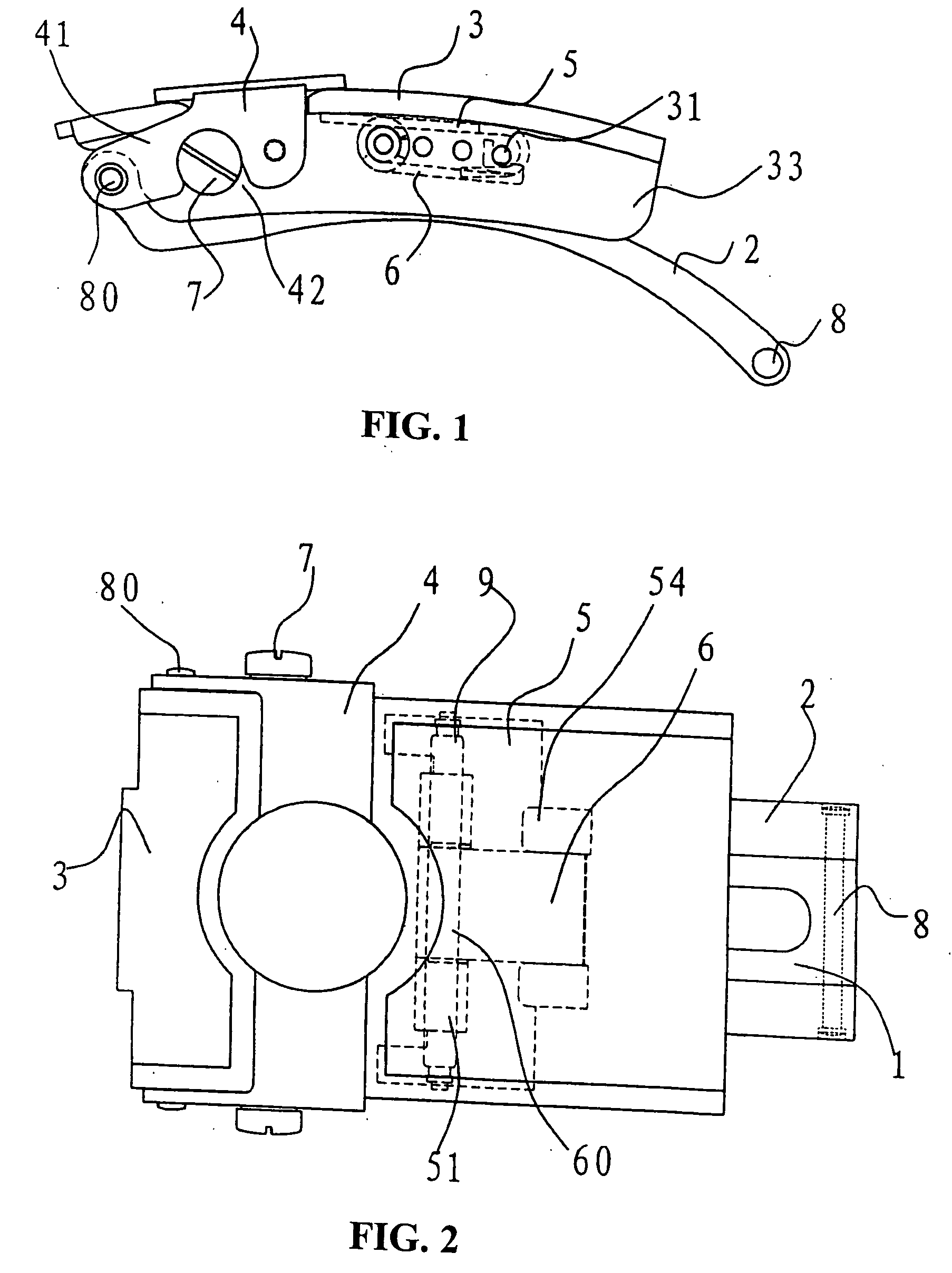
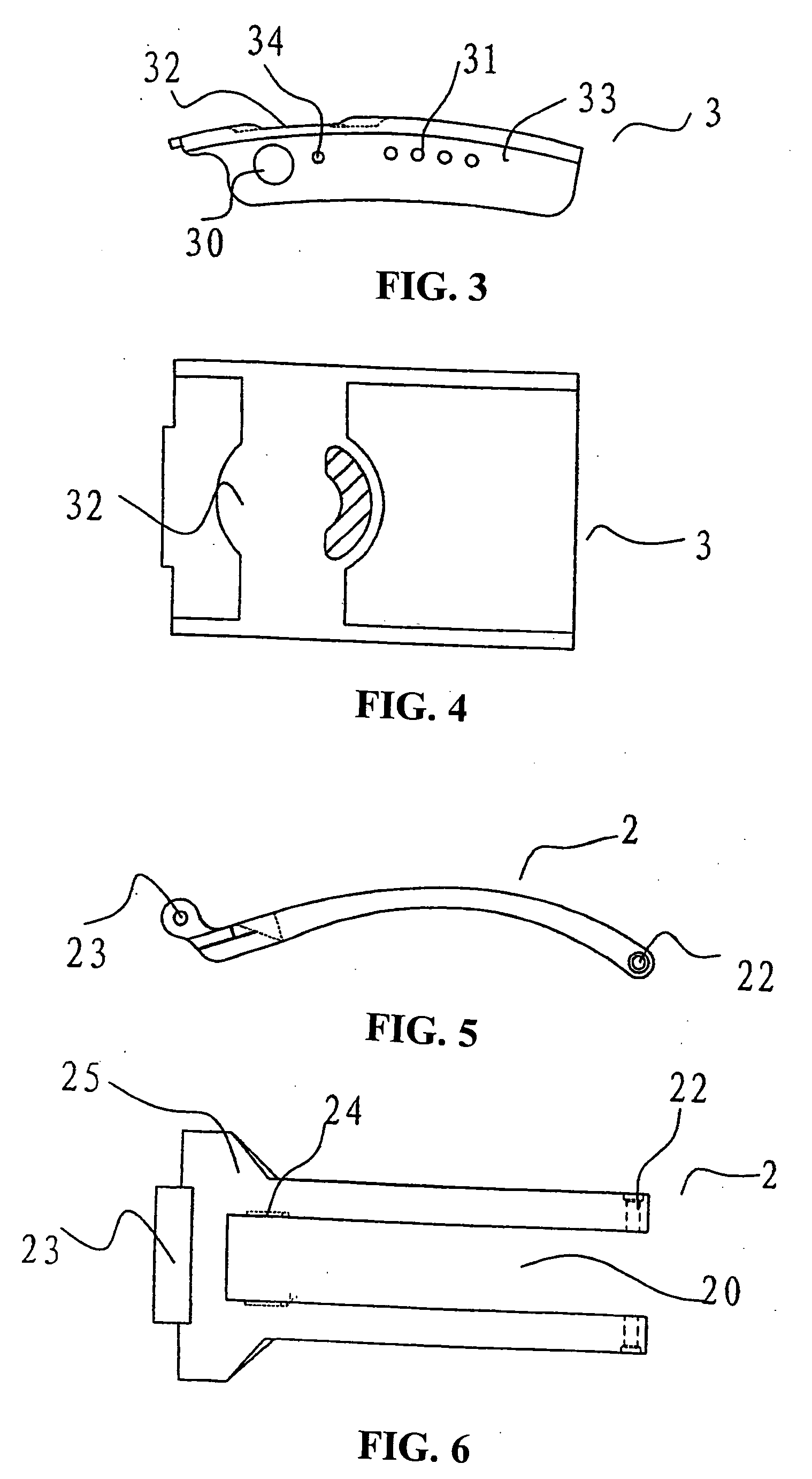
[0034] As shown in FIGS. 1 and 2, the clasp assembly of the present invention includes an inner bend plate 1, and an outer bend plate 2, a clasp cap 3, a security cover 4, a hook clasp 5, a locking clasp 6, a screw 7, a rivet 8 and an elastic shaft 9. The inner bend plate 1 is fitted into the outer bend plate 2, a convex clasp 15 and a concave clasp 16 therein engaging with each other so that the inner bend plate 1 and the outer bend plate 2 are combined into one bend plate, as shown in FIGS. 6 and 8. The clasp plate 3 is movably connected with the inner bend plate 1 through the screw 7, and can pivot slightly about the screw 7. The hook clasp 5 and the locking clasp 6 are mounted on the elastic shaft 9 in the inner side of the clasp cap 3, wherein the hook clasp 5 can pivot slightly about the shaft 9 and the locking clasp 6 can pivot about it in a large angle range. The watch chain 18 is connected with the hook clasp 5 and locked by the locking clasp 6. FIG. 14 shows the operation ...


PUM


Abstract

A clasp assembly, which can be disconnected or connected with a watch chain quickly, includes a clasp cap, an inner bend plate, outer band plate, a screw, a rivet and an elastic shaft. The inner bend plate comprises an arc plate body and two cylindrical bodies, the two cylindrical bodies disposed on one end of the plate body, a thread hole provided on the surface of a distal end of each cylindrical body, a through hole provided on the other end of the plate body and a convex clasp provided on each side of the plate body. A groove is provided in the middle of the outer bend plate and a through hole is formed on one end of the out bend plate, which comprises two sections spaced by the groove, and linked with the through hole of the inner bend plate by engaging with the rivet pivotally. A through hole is formed on the other end of the outer bend plate which remains integral, and concave clasps are disposed symmetrically on the inner sides of the outer bend plate. The clasp cap is pivotally connected with the thread hole of the inner bend plate by the screw, through holes disposed in two side plates of the clasp cap. A hook clasp and a locking clasp for being connected with the watch chain are mounted on the elastic shaft engaging with the through holes, the locking clasp fitting into the hook clasp. A security cover is pivotally mounted on the rivet connecting the outer bend plate with the watch chain.

Description

CROSS-REFERENCE TO RELATED APPLICATION [0001] This application claims the priority benefit of Chinese Utility Model Application No. 2004200592487 filed on May 28, 2004, the content of which is hereby incorporated in its entirety herein by reference. FIELD OF THE INVENTION [0002] The present invention relates to a clasp assembly, particularly to a clasp assembly which can be connected or disconnected with a watch chain quickly. DESCRIPTION OF THE PRIOR ART [0003] In the prior art, the structure of a clasp assembly for a metallic watch chain is very complicated, involves a lot of parts, and is difficult to assemble and maintain. In order to solve this problem, a new clasp for a watch chain with fewer components and a simple structure was developed, such as that disclosed in Chinese Patent No. 99200269.9, which has been used and accepted widely. As the developments of economy and technology, multifunction watches are designed to incorporate other functions into a watch. For example, a ...

Claims


Application Information

Patent Timeline
Patent Type & Authority Applications(United States)
IPC IPC(8): A44C5/18A44C5/24
CPCA44C5/24Y10T24/2155Y10T24/4782
Inventor HO, KAI CHEUNG
Owner JOLLY HOPE ENTERPRISE
Why Eureka
Try Eureka