Coupling assembly and method for connecting and disconnecting a shaft assembly

a technology of coupling assembly and shaft assembly, which is applied in the direction of couplings, rod connections, manufacturing tools, etc., can solve the problems of difficult to go back and disconnect the two without time-consuming and disadvantageous unbolting processes, the bolting system is not very suitable for use in processes, and the unbolting process may be undesirable. , to achieve the effect of quick connection and disconnecting the shaft, the effect of quick connection and disconnecting

Active Publication Date: 2008-02-12
SPX FLOW INC
View PDF15 Cites 9 Cited by
  • Summary
  • Abstract
  • Description
  • Claims
  • Application Information

AI Technical Summary

Benefits of technology

[0006]The foregoing needs are met, to a great extent, by the present invention, wherein in one aspect an apparatus is provided that in some embodiments provides an apparatus and method which can be fitted onto a drive output shaft and onto an impeller shaft, and which can be used to quickly connect and disconnect the shafts to and from each other. Thus, enabling a drive to be quickly connected and disconnected to and from a mixing assembly.

Problems solved by technology

A disadvantage to this arrangement is that it is relatively permanent and once the drive output shaft's coupling half is bolted to the impeller shaft's coupling half, it is now difficult to then go back and disconnect the two without time consuming and disadvantageous unbolting processes.
Therefore, these bolting systems are not very suitable for use in processes where it is often necessary to disconnect the motor output shaft from the impeller shaft in order to disconnect the drive from the rest of the mixing assembly.
Because this known sterilization process involves removing the drive, the foregoing time consuming unbolting and bolting processes may be undesirable.

Method used


Image

  • Coupling assembly and method for connecting and disconnecting a shaft assembly
  • Coupling assembly and method for connecting and disconnecting a shaft assembly
  • Coupling assembly and method for connecting and disconnecting a shaft assembly

Examples


Embodiment Construction

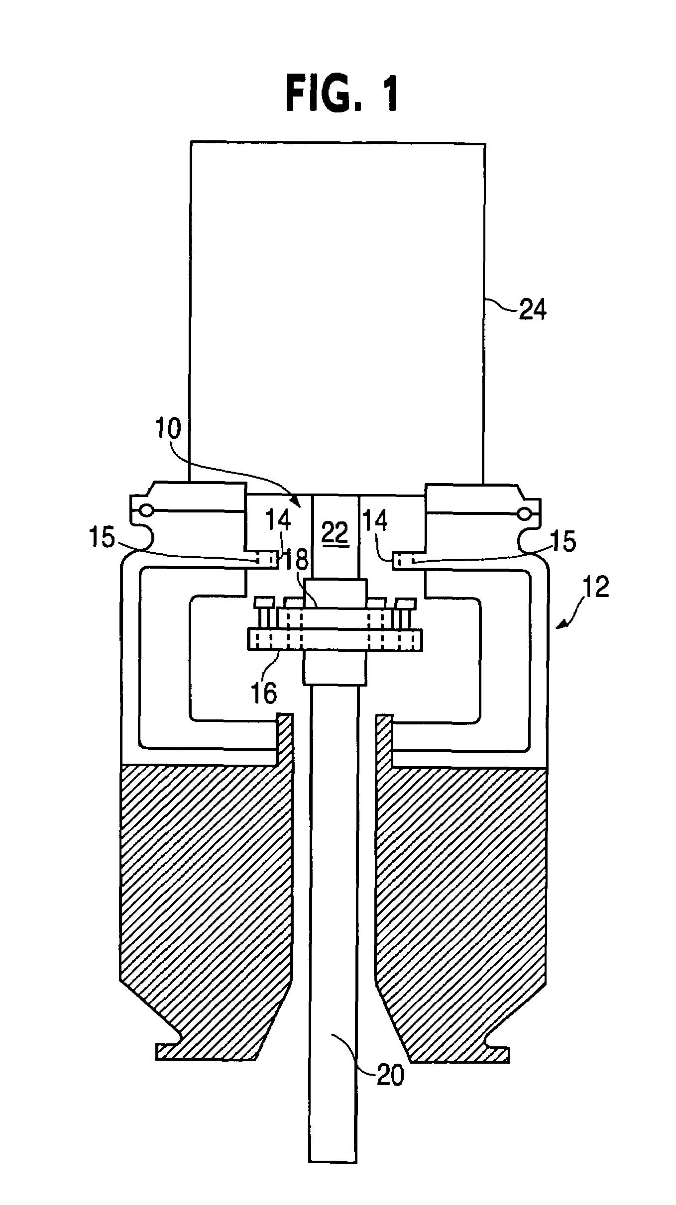
[0018]An embodiment in accordance with the present invention provides an apparatus and method which can be fitted onto a drive output shaft and onto an impeller shaft, and which can be used to quickly connect and disconnect the shafts to and from each other. The present invention may be suitable for use in processes where it is often necessary to disconnect a drive output shaft from the impeller shaft in order to disconnect the motor from the rest of the mixing assembly. For example in the biotech industry, in order to provide a sterile mixing assembly, the mixing assembly's drive is removed and the rest of the mixing assembly is placed into an autoclave where it is sterilized.

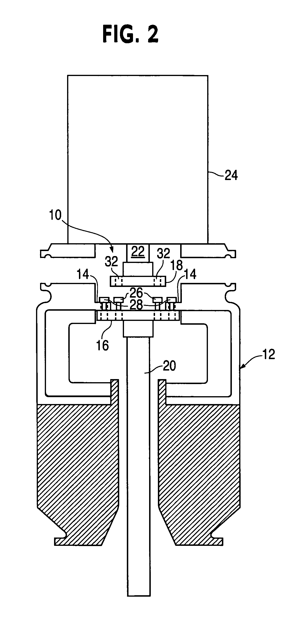
[0019]Preferred embodiments of the invention will now be described with reference to the drawing figures, in which like reference numerals refer to like parts throughout. Turning to FIG. 1, a coupling assembly 10 is depicted in a configuration located within a housing 12. The housing 12 may be, for example, re...


PUM


Abstract

A coupling assembly that can be used to quickly connect and disconnect an impeller shaft to and from a drive output shaft. A portion of the coupling assembly can be used to secure the impeller shaft inside a mixing vessel so that the impeller shaft can remain secure inside the mixing vessel when the drive is disconnected. The coupling assembly has a first and a second coupling half, a first group of locking pens that extend from the first coupling half and can pass through openings formed in the second coupling half, and second group of locking pins that extend from the first coupling half and can pass through openings formed in the top region of the mixing vessel.

Description

FIELD OF THE INVENTION[0001]The present invention relates generally to the field of couplings, for example, couplings that connect an impeller shaft to a drive output shaft. More particularly, the present invention relates to couplings that can be used to quickly connect and disconnect an impeller shaft to and from a drive output shaft.BACKGROUND OF THE INVENTION[0002]Mixing devices are in wide use in industry, and many mixing devices include a large mixing vessel which contains a liquid to be mixed, and a typically vertical impeller shaft running down some or all of the vertical length inside the mixing vessel. The impeller shaft is typically rotatably driven by a motor output shaft, usually located at the top of the mixing vessel, and at one or several locations on the length of the impeller shaft radially extending impellers are mounted which have paddles or blade type features along some or all of the length and which mix and / or otherwise impart energy to the fluid inside the mi...

Claims


Application Information

Patent Timeline
Patent Type & Authority Patents(United States)
IPC IPC(8): F16D1/112F16D1/116
CPCF16D1/033F16D1/112Y10T403/7007Y10T403/64Y10T403/7009Y10T403/7005F16B2200/50
Inventor HU, XIAOBINGKOCIENSKI, ANTHONY C.
Owner SPX FLOW INC
Why Eureka
Try Eureka