Golf ball with spherical polygonal dimples

a golf ball and polygonal technology, applied in the field of golf balls, can solve the problems of reducing the aerodynamic effectiveness of the dimple, the susceptibility of the small dimple to paint flooding, and the ineffectiveness of the small dimple in reducing drag and increasing lift, so as to achieve the effect of improving the aerodynamic characteristics

Inactive Publication Date: 2005-12-01
ACUSHNET CO
View PDF29 Cites 34 Cited by
  • Summary
  • Abstract
  • Description
  • Claims
  • Application Information

AI Technical Summary

Benefits of technology

[0012] The present invention is also directed to a golf ball with improved aerodynamic characteristics.

Problems solved by technology

This is the primary source of drag for golf balls.
In arranging the dimples, an attempt is made to minimize the space between dimples, because such space does not contribute to the aerodynamic performance of the ball.
However, in reality small dimples are not as effective in decreasing drag and increasing lift.
This results at least in part from the susceptibility of small dimples to paint flooding.
Paint flooding occurs when the paint coat on the golf ball fills the small dimples, and consequently decreases the dimple's aerodynamic effectiveness.
On the other hand, a smaller number of large dimples also begin to lose effectiveness.
However, the circular perimeters of conventional dimples to a large extent limit the maximum dimple density attainable, due to the irregular shape of the spaces between the circular dimples on the ball surface.
None of these references, however, discloses dimples with spherical or substantially spherical depressions.
It has also been demonstrated that dimples with polyhedron depressions do not perform as well aerodynamically as dimples with spherical or substantially spherical depressions.

Method used


Image

  • Golf ball with spherical polygonal dimples
  • Golf ball with spherical polygonal dimples
  • Golf ball with spherical polygonal dimples

Examples


Embodiment Construction

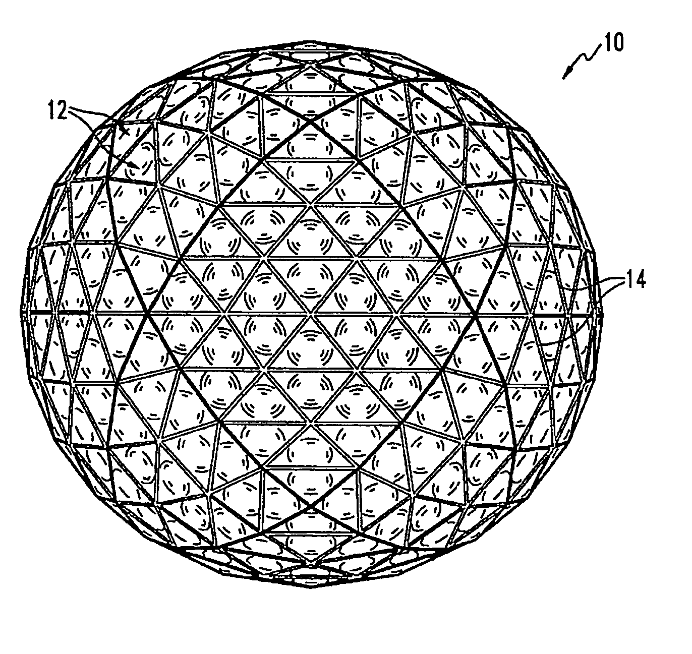
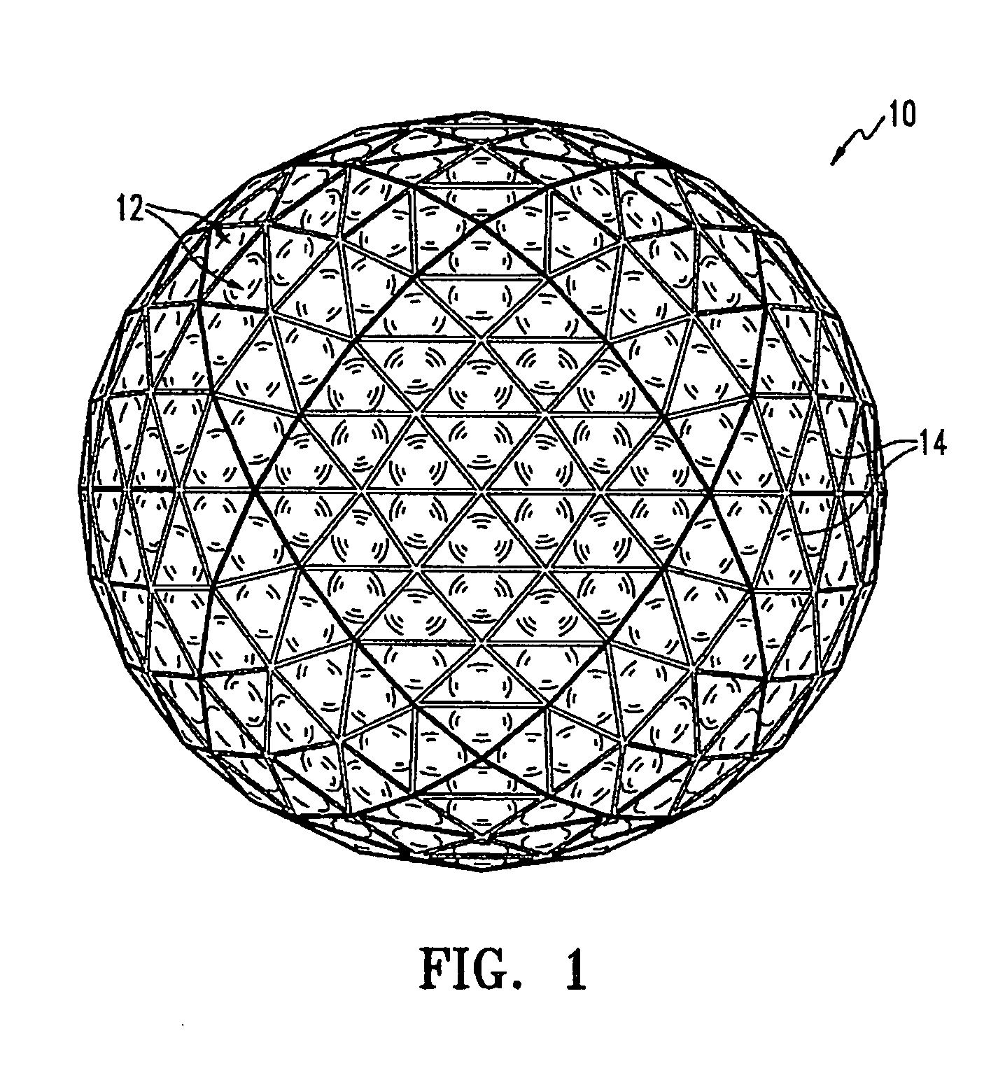
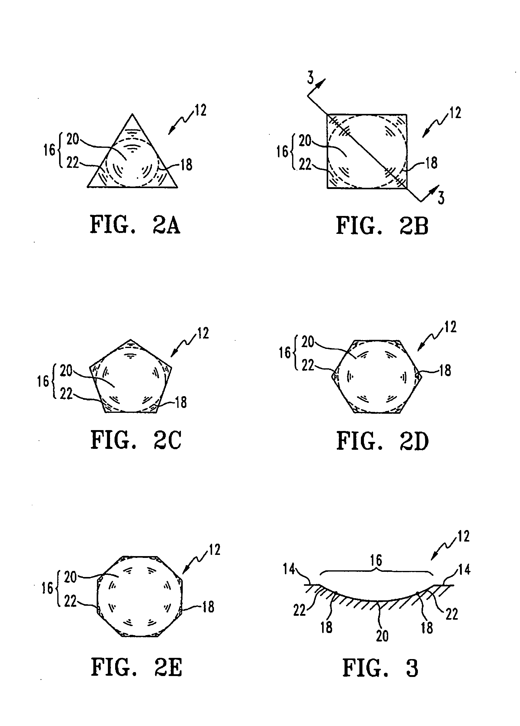
[0044] As shown generally in FIG. 1 where like numbers designate like parts, reference number 10 broadly designates a golf ball 10 having a plurality of dimples 12 with polygonal perimeter of the present invention separated by outer undimpled or land surfaces 14. Each dimple preferably comprises a polygonal perimeter and a substantially spherical depression 16. The polygonal perimeters of dimples 12 are shown in FIG. 1 as triangular. The present invention, however, is not so limited, and dimples 12 with any regular or irregular polygonal-shaped perimeter with 3 or more sides, and a concave, substantially spherical depression are within the scope of the present invention, as further discussed below. More particularly, dimples formed of more than one perimeter shape are employed. For example, a portion of a dimple perimeter can be a portion of a triangle and the other portion of the dimple perimeter can be a portion of a hexagon. The perimeter may have any number of sides of unequal l...


PUM


Abstract

A golf ball includes an outer spherical surface and a plurality of dimples formed thereon. In accordance to one aspect of the invention, the dimples have a polygonal perimeter and a concave depression. The concave depression satisfies only two of the following conditions: a substantially circular depression perimeter, a substantially spherical shape, and the depression contacting the perimeter of the dimple. In accordance to another aspect of the invention, one or more sides of the polygonal perimeter may be non-linear or curved. The dimples of the present invention may fill the ball's entire outer surface, or the dimples may occupy a predetermined pattern on the ball. The predetermined pattern may also include one or more channels or raised beads on the surface of the ball.

Description

RELATED APPLICATIONS [0001] This application is a continuation-in-part of U.S. application Ser. No. 11 / 141,093, filed on May 31, 2005, which is a divisional application of U.S. application Ser. No. 10 / 077,090, filed on Feb. 15, 2002.FIELD OF THE INVENTION [0002] The present invention relates to golf balls, and more particularly, to a golf ball having improved dimples. BACKGROUND OF THE INVENTION [0003] Golf balls generally include a spherical outer surface with a plurality of dimples formed thereon. Conventional dimples are depressions on the golf balls' surface that reduce drag and increase lift. Drag is the air resistance that opposes the golf ball's flight direction. As the ball travels through the air, the air that surrounds the ball has different velocities thus, different pressures. The air exerts maximum pressure at a stagnation point on the front of the ball. The air then flows around the surface of the ball with an increased velocity and reduced pressure. At some separation...

Claims


Application Information

Patent Timeline
Patent Type & Authority Applications(United States)
IPC IPC(8): A63B37/00A63B37/12
CPCA63B37/0004A63B37/0012A63B37/0009A63B37/0006A63B37/00065
Inventor MORGAN, WILLIAM E.AOYAMA, STEVEN
Owner ACUSHNET CO
Why Eureka
Try Eureka