Vortex generator arrangement for an airfoil

Active Publication Date: 2014-08-07
LM WIND POWER AS
View PDF31 Cites 18 Cited by
  • Summary
  • Abstract
  • Description
  • Claims
  • Application Information

AI Technical Summary

Problems solved by technology

In wind turbine blade aerodynamics, boundary layer separation occurs when an airfoil profile experiences a relati

Method used


Image

  • Vortex generator arrangement for an airfoil
  • Vortex generator arrangement for an airfoil
  • Vortex generator arrangement for an airfoil

Examples


Embodiment Construction

[0090]An embodiment of the invention will now be described, by way of example only, with reference to the accompanying drawings, in which:

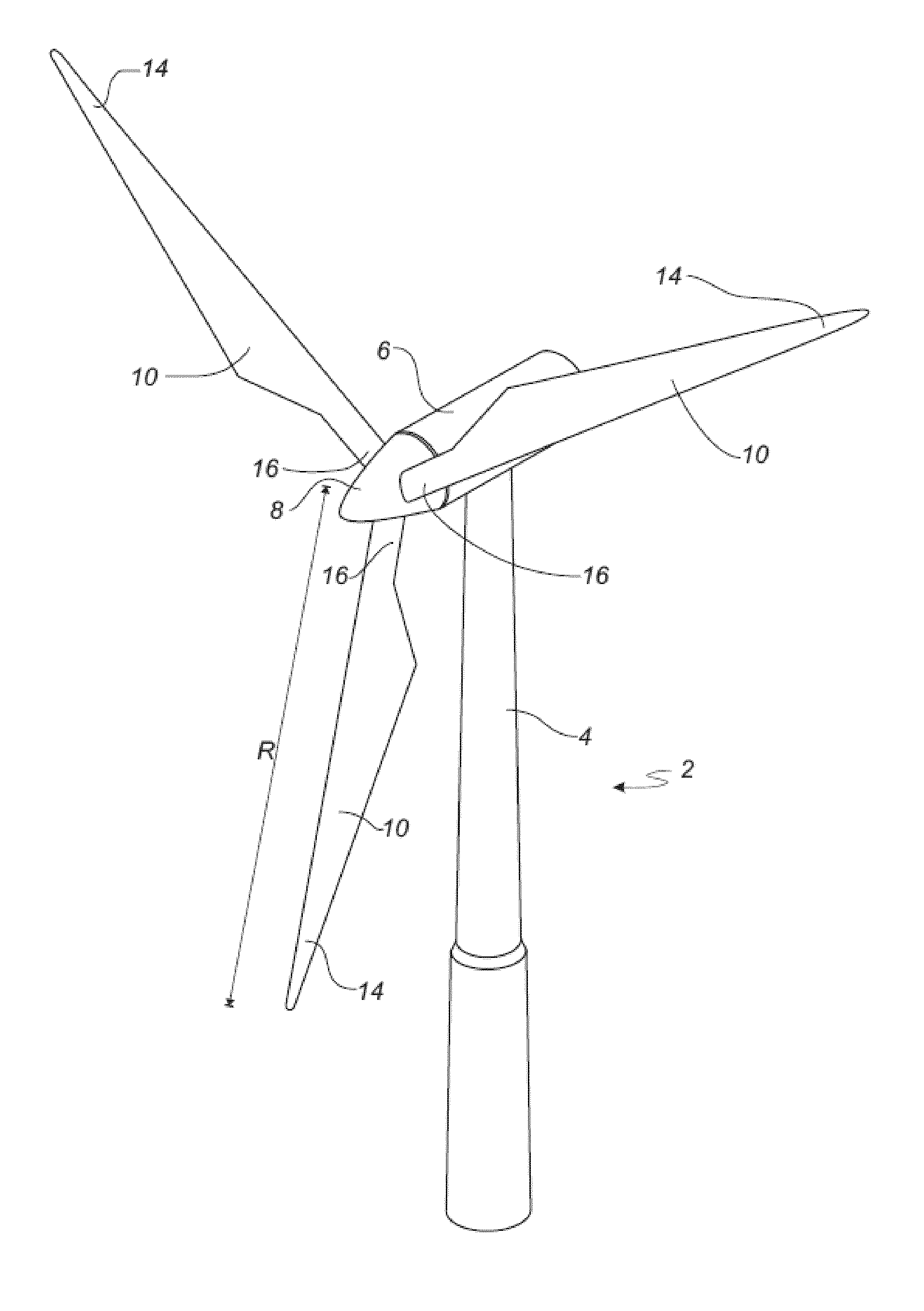
[0091]FIG. 1 shows a wind turbine;

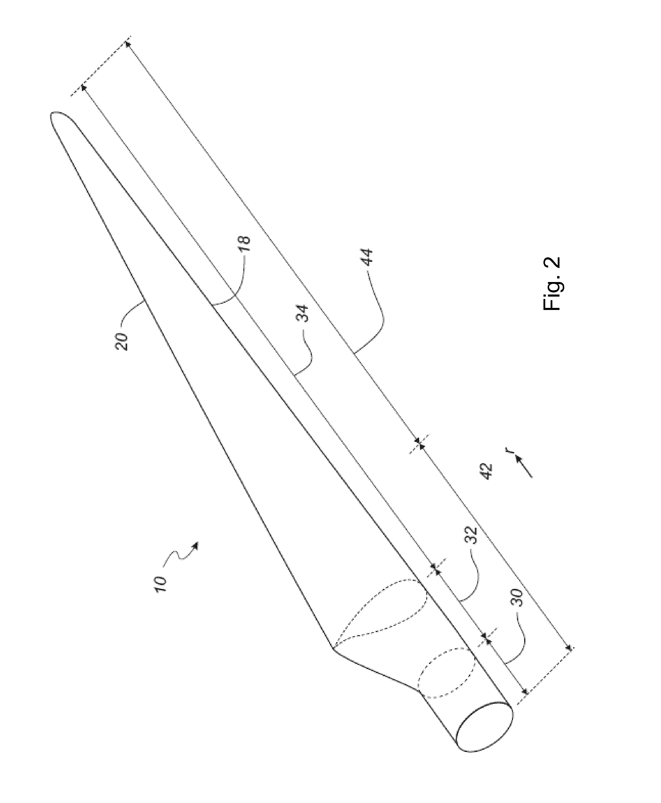
[0092]FIG. 2 shows a schematic view of a wind turbine blade according to the invention;

[0093]FIG. 3 shows a schematic view of an airfoil profile of the blade of FIG. 2;

[0094]FIG. 4 shows an enlarged view of an arrangement of vortex generators according to the invention;

[0095]FIG. 5 shows a plot of the lift coefficient against the angle of attack from experimental results of two embodiments of the invention in comparison with prior art systems;

[0096]FIG. 6 shows a plot of the drag coefficient against the angle of attack from experimental results of two embodiments of the invention in comparison with prior art systems; and

[0097]FIG. 7 shows a plot of the (lift coefficient / drag coefficient) against the angle of attack from experimental results of two embodiments of the invention in comparison with prior art systems a...


PUM


Abstract

A particular arrangement of vortex generators for an airfoil is described. The vortex generators are provided in pairs, preferably on a wind turbine blade, wherein by arranging the vortex generators according to specified characteristics, a surprising improvement in blade performance is provided over the prior art systems.

Description

FIELD OF THE INVENTION[0001]The present invention relates to an arrangement of vortex generators in an airfoil, in particular on a wind turbine blade.BACKGROUND OF THE INVENTION[0002]In wind turbine blade aerodynamics, boundary layer separation occurs when an airfoil profile experiences a relatively high angle of attack, which can cause a separation of attached airflow from the suction side of the airfoil. Such boundary layer separation results in a reduction in lift generated by the airfoil.[0003]Vortex generators are used on wind turbine blades in order to induce turbulent airflow vortices as the aerodynamic profile of the blade is impacted upon by an incident airflow. The creation of these vortices acts to delay separation of the attached airflow from the aerodynamic profile, thereby improving blade performance for a wide range of angles of attack.[0004]A 2006 paper by Godard et al. [G. Godard & M. Stanislas; Control of a decelerating boundary layer. Part 1: Optimization of passi...

Claims


Application Information

Patent Timeline
IPC IPC(8): B64C23/06
CPCB64C23/06F01D5/145F03D1/0633F05D2240/30Y02E10/72F05B2240/3062F03D1/0675Y02T50/10F05B2240/132F05B2240/301
Inventor WURTH, INESMADSEN, JESPERHANSEN, ROLFMULLER, OLAF
Owner LM WIND POWER AS
Why Eureka
Try Eureka