
High velocity ammunition round

a high-speed, ammunition technology, applied in the direction of ammunition fuzes, ignitors, weapons, etc., can solve the problems of variable gun powder charge, significant and uncontrollable source of error in the accuracy of long-range sniper rounds, etc., to reduce the time of flight to a target and long-range accuracy

Inactive Publication Date: 2011-09-08
GLASSER ALAN Z
View PDF50 Cites 20 Cited by
  • Summary
  • Abstract
  • Description
  • Claims
  • Application Information

AI Technical Summary

Benefits of technology

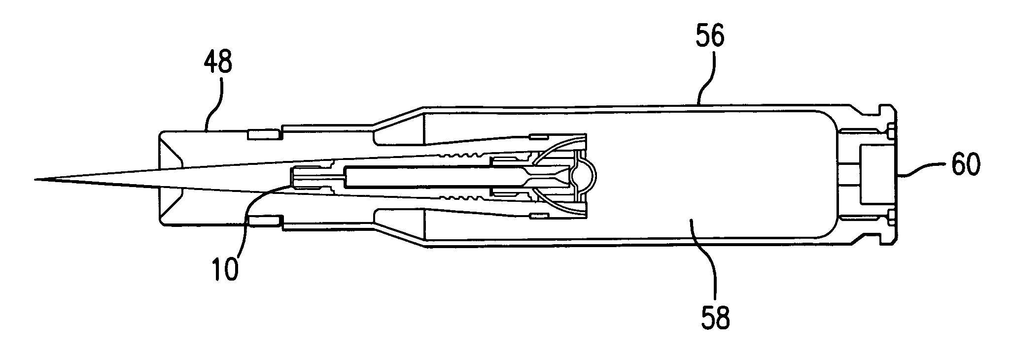
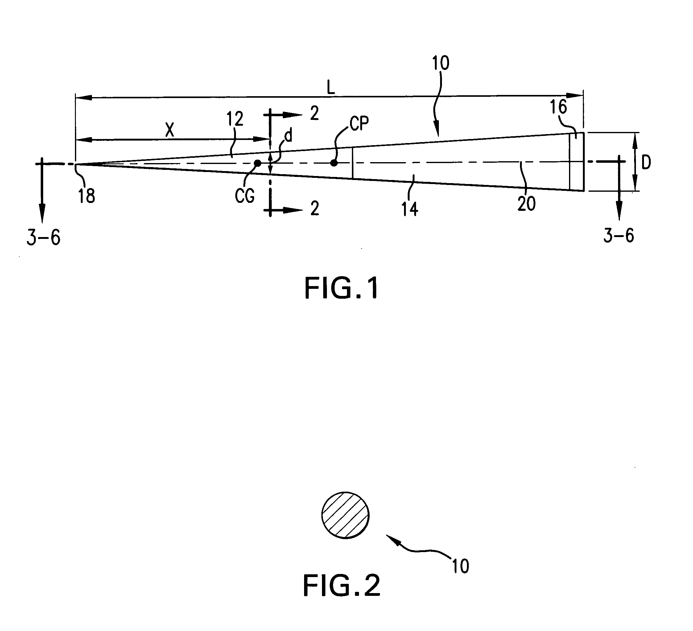
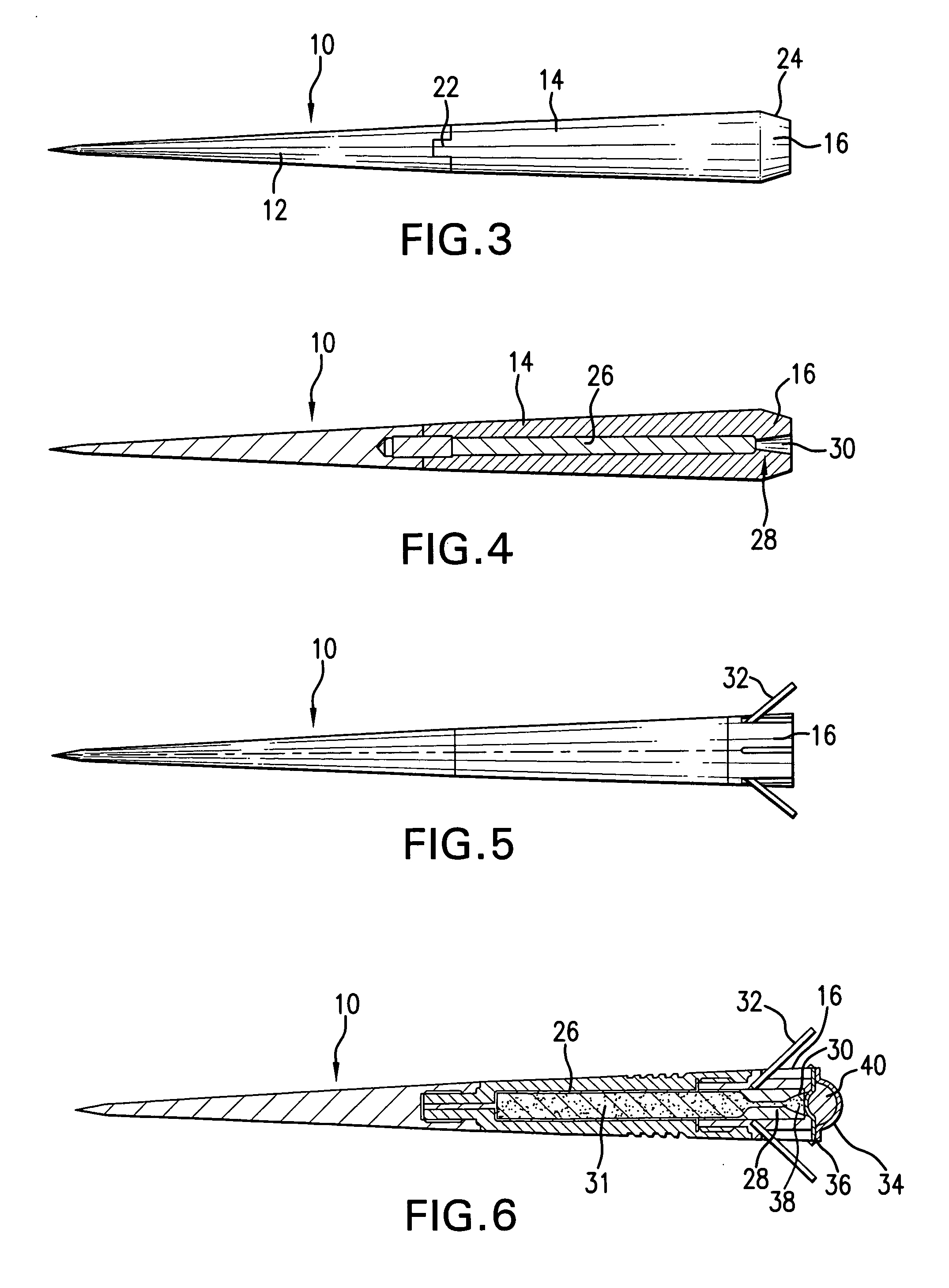
[0008]A sub-caliber bullet with an aerodynamic shape has long-range accuracy due to a high muzzle velocity and reduced time of flight to a target. The bullet has a forward portion, a mid-portion and an aft portion. The forward portion has a density in excess of 10 g / cm3 while the mid-portion has a lower density. In one embodiment, the bullet has an aspect ratio of at least 5:1 and a nose profile that satisfies a Power Law equation:d=D*(x / L)n  (1)where d is the diameter at a point along the length L, D is a maximum bullet diameter, L is the length, x is a distance rearward from a nose of the bullet and n is a Power Law exponent that is between 0.5 and 0.75. In some embodiments, a blind bore extends into the mid-portion from the aft portion and a sustainer propellant within the blind bore ignites as the bullet exits a gun muzzle to provide a thrust to overcome aerodynamic drag, thereby maintaining the bullet velocity and in certain embodiments accelerating the bullet.
[0009]The aerodynamic properties of the sub-caliber bullet are enhanced when the Power Law exponent, n, is approximately 0.67 and the aspect ratio is approximately 10:1. Ballistic stability is enhanced by an aft portion that either has a boat tail, flat base configuration or has a plurality of outwardly and rearwardly extending whiskers symmetrically disposed about its circumference.

Problems solved by technology

A significant, and uncontrollable, source of error in the accuracy of a long range sniper round is wind.
Other sources of error include the effect of gravity during a long time of flight, variations in gun powder charge and drag.

Method used


Image

  • High velocity ammunition round
  • High velocity ammunition round
  • High velocity ammunition round

Examples


examples

[0064]Advantages of the bullet desCribed herein may be better understood by the following prophetic Example:

[0065]In the Table illustrated in FIG. 15, various bullet parameters are calculated by analytic methods and compared to properties of conventional bullets. The properties of the conventional bullets were determined by data published by ammunition companies. Significant improvements by the bullets disclosed herein are noted, particularly for muzzle velocity, bullet drop at 1 km and time of flight to target, as well as accuracy.

[0066]The round has another reason for increased accuracy and that relates to the aerodynamics of the bullet reacting to side wind forces and crabbing into the wind. When the flight body is flying to the target with the sustainer compensating for drag, the velocity of the round, vaxial, is constant and the drag force is exactly compensated by the force of the sustainer's thrust. If that weren't true, the bullet would either accelerate of decelerate (force...


PUM


Abstract

A sub-caliber bullet with an aerodynamic shape has long-range accuracy due to a high muzzle velocity and reduced time of flight to a target. The bullet has a forward portion, a mid-portion and an aft portion. The forward portion has a density in excess of 10 / cm3 while the mid-portion has a lower density. The bullet has an aspect ratio of at least 5:1 and a diameter, d, that satisfies a Power Law equation:d=D*(x / L)nwhere D is a maximum bullet diameter, L is the length, x is a distance rearward from a nose of the bullet and n is a Power Law exponent that is between 0.5 and 0.75. In some embodiments, a blind bore extends into the mid-portion from the aft portion and a sustainer propellant within the blind bore ignites as the bullet exits a gun muzzle to provide a velocity boost and to overcome aerodynamic drag.

Description

CROSS REFERENCE TO RELATED APPLICATION(S)[0001]N.A.U.S. GOVERNMENT RIGHTS[0002]N.A.BACKGROUND[0003]1. Field of the Invention[0004]Disclosed herein is a high velocity ammunition round that more particularly is sub-caliber with a high density forward portion and a lower density aft portion. Optionally, a sustainer propellant or a base-bleed propellant may be contained within the aft portion.[0005]2. Description of the Related Art[0006]A significant, and uncontrollable, source of error in the accuracy of a long range sniper round is wind. Other sources of error include the effect of gravity during a long time of flight, variations in gun powder charge and drag. Drag causes the bullet velocity to decrease which increases the time of flight to a target. Types of drag that act on a bullet are wave drag (the drag force resulting from aerodynamic shock waves), skin friction drag (the friction between the airstream and the surface of the projectile) and base drag (a vacuum effect at the back...

Claims


Application Information

Patent Timeline
IPC IPC(8): F42B14/08F42B14/06F42B12/44
CPCF42B12/44Y10S102/703F42B14/08F42B14/06F42B12/34F42B12/74F42B5/025F42B12/06F42B10/46F42B14/061F42B10/40F42B10/08
Inventor GLASSER, ALAN Z.
Owner GLASSER ALAN Z
Learn More