Golf ball dimples with spiral depressions

a golf ball and spiral depression technology, applied in the field of golf balls, can solve the problems of small dimples not being very effective in reducing drag and increasing lift, affecting the aerodynamic affecting the performance of the ball, so as to promote the energizing of the aerodynamic boundary layer, improve the aerodynamic characteristics, and prevent premature wear and tear.

Inactive Publication Date: 2008-10-23
ACUSHNET CO
View PDF24 Cites 19 Cited by
  • Summary
  • Abstract
  • Description
  • Claims
  • Application Information

AI Technical Summary

Benefits of technology

[0010]Accordingly, the present invention is directed to a golf ball with improved depressions, whether the depressions being directly on the surface of the ball or within the confines of land area in the concave surface of a dimple. The present invention is also directed to a golf ball with improved aerodynamic characteristics. These and other embodiments of the prevent invention are realized by a golf ball comprising a spherical outer land surface and a plurality of dimples or depressions formed thereon. Each depression, whether on the ball surface or within the confines of a dimple, comprise at least one spiral structure to promote the energizing of the aerodynamic boundary layer over the contour surface of the ball. The un-dimpled land surface, therefore, remains robust to prevent premature wear and tear. The dimples can have a myriad of shapes and sizes and may be distributed in any pattern, concentration or location.

Problems solved by technology

This is the primary source of drag for golf balls.
In arranging the dimples, an attempt is made to minimize the space between dimples, because such space does not improve aerodynamic performance of the ball.
However, in reality small dimples are not always very effective in decreasing drag and increasing lift.
This results at least in part from the susceptibility of small dimples to paint flooding.
Paint flooding occurs when the paint coat on the golf ball partially fills the small dimples, and consequently decreases their aerodynamic effectiveness.
On the other hand, a smaller number of large dimples also begins to lose effectiveness.
The rough surface on the land surface of the ball may decrease the aesthetic appearance of the ball.
Furthermore, these small craters may be covered by paint flooding.
These smooth irregular dimple surfaces, however, might not efficiently energize the boundary layer flow over the dimples.
Since as the land surface decreases, the susceptibility of the ball to premature wear and tear by impacts with the golf club increases.

Method used


Image

  • Golf ball dimples with spiral depressions
  • Golf ball dimples with spiral depressions
  • Golf ball dimples with spiral depressions

Examples


Embodiment Construction

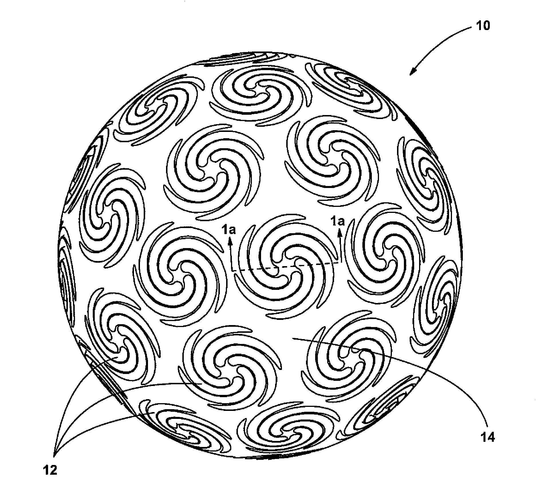
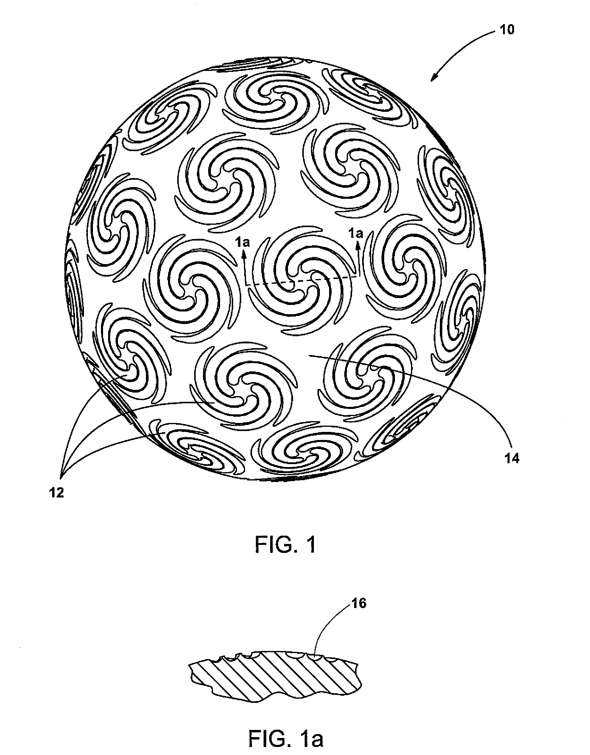
[0023]As shown generally in FIGS. 1, and 1a, where like numbers designate like parts, reference number 10 broadly designates a golf ball 10 having a plurality of spiral depressions 16 on the surface of the ball 10 and separated by un-dimpled surface 14. These spiral depressions 16 depicted herein are atypical of the conventional dimple site 12 that is well known in the industry.

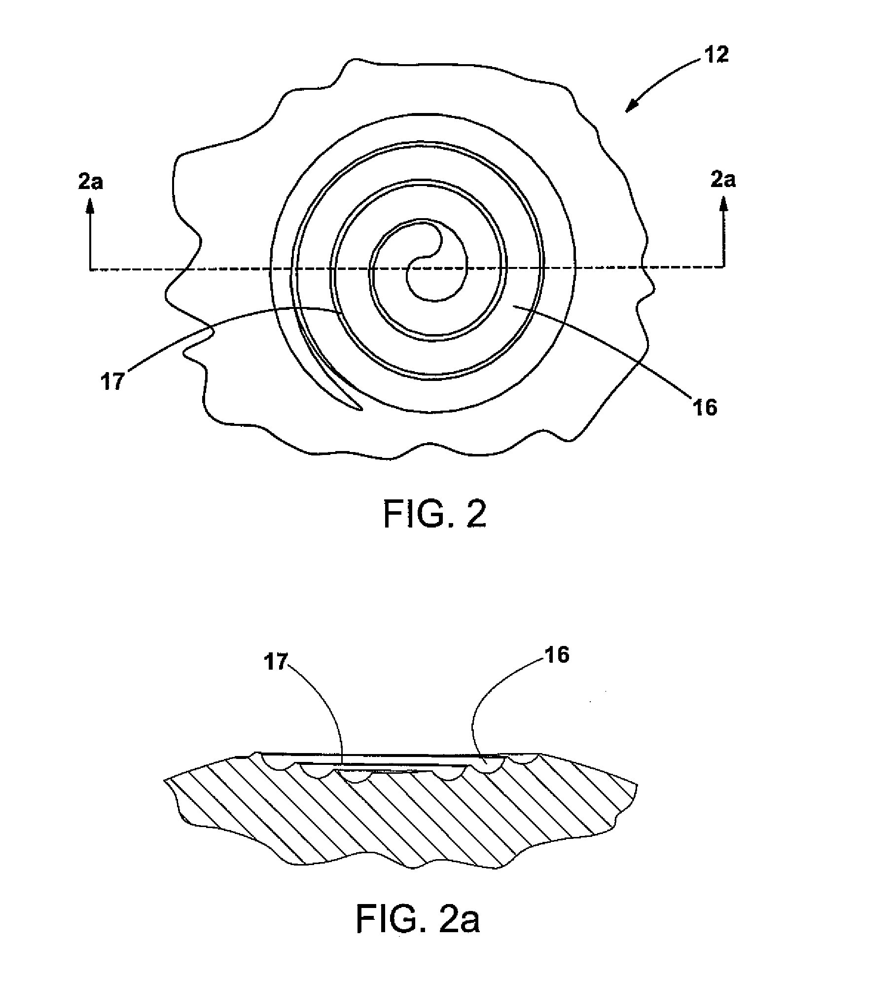
[0024]Other embodiments of the invention are shown in FIGS. 2-7 wherein the spiral depressions 16 are on the concave inner surface of a dimple 12, the dimples 12 having at least one spiral depression 16 defined thereon to further agitate or energize the boundary layer flow over the dimples 12 and to reduce the tendency for separation of the turbulent boundary layer around the golf ball in flight. As described below, the dimples 12 may have many shapes and sizes, and the spiral depressions may have many sizes and shapes, as long as they contribute to the agitation of the air flowing over the dimples.

[0025]FIGS...


PUM


Abstract

A golf ball includes a spherical outer surface and a plurality of dimples formed thereon. The dimples have an inner land surface with at least one spiral depression either disposed or superimposed on the inner land surface to energize or agitate the airflow over the dimpled surfaces to increase the aerodynamic performance of the golf ball. The spiral depression may turn clockwise or counterclockwise and can be either spaced apart, touching or overlapping each other. While the dimples may be circular, polygonal, triangular or elliptical, dimples having a cross section greater than 0.18 inch are preferred. The dimples may also comprise spiral depressions directly on the spherical surface of the ball.

Description

FIELD OF THE INVENTION[0001]The present invention relates to golf balls, and more particularly, to golf balls that have dimples which contain spiral depressions or are a product of spiral depressions directly on the surface of the ball.BACKGROUND OF THE INVENTION[0002]Golf balls generally include a spherical outer surface with a plurality of dimples formed thereon. Conventional dimples are circular depressions that reduce drag and increase lift. These dimples are formed where a dimple wall slopes away from the outer surface of the ball forming the depression.[0003]Drag is the air resistance that opposes the golf ball's flight direction. As the ball travels through the air, the air that surrounds the ball has different velocities and thus, different pressures. The air exerts maximum pressure at a stagnation point on the front of the ball. The air then flows around the surface of the ball with an increased velocity and reduced pressure. At some separation point, the air separates from...

Claims


Application Information

Patent Timeline
Patent Type & Authority Applications(United States)
IPC IPC(8): A63B37/14
CPCA63B37/0007
Inventor OLSON, TRACI L.AOYAMA, STEVEN
Owner ACUSHNET CO
Why Eureka
Try Eureka