Multi-stage cryogenic acid gas removal

a cryogenic acid and gas removal technology, applied in the field of gas separation, can solve the problems of high energy consumption of the separation process and the cosub>2 /sub>compression process, unattractive economic conditions, and significant quantity of energy, either in steam or electricity, is required to regenerate solvent, etc., to achieve the effect of increasing the quantity of acid gas and lessening the power needed to pressurize acid gas streams

Inactive Publication Date: 2007-09-27
TENNESSEE VALLEY AUTHORITY
View PDF9 Cites 48 Cited by
  • Summary
  • Abstract
  • Description
  • Claims
  • Application Information

AI Technical Summary

Benefits of technology

[0019] A still further object of this invention is to generate the multiple acid gas product streams with a pressure as high as practicable in each acid gas product stream so as to lessen the power needed to pressurize the acid gas streams, most preferably for sequestration.
[0020] A further object of thi

Problems solved by technology

Although many commercial processes are available to produce purified hydrogen and CO2, the energy consumed by undertaking both the separation process and the CO2 compression process is quite high, making current processes economically unattractive.
A chief drawback to these solvent-based acid gas removal processes is that a significant quantity of energy, either in the form of steam or electricity, is required to regenerate the solvent.
The very act of diluting the acid gases within a solvent means that significant energy is required to reconstitu

Method used


Image

  • Multi-stage cryogenic acid gas removal
  • Multi-stage cryogenic acid gas removal
  • Multi-stage cryogenic acid gas removal

Examples


example

[0096] In order that those skilled in the art may better understand how the present invention can be practiced, the following example is given by way of illustration only and not necessarily by way of limitation, since numerous variations thereof will occur and will undoubtedly be made by those skilled in the art without substantially departing from the true and intended scope and spirit of the instant invention herein taught and disclosed.

[0097] Pressures, temperatures, compositions, flow rates and other stream properties presented in the example below were calculated using ChemCAD® process simulation software, a product of Chemstations, Inc. headquartered in Houston Tex. Collectively these calculations are referred to herein as a computer simulation model or simply as a model. The software version used was CC-Steady State, version 5.3. ChemCAD® is a computer simulation program widely used throughout the chemical process industry and considered to be state of the art. As with any ...


PUM

PropertyMeasurementUnit
Temperatureaaaaaaaaaa
Freezing pointaaaaaaaaaa

Abstract

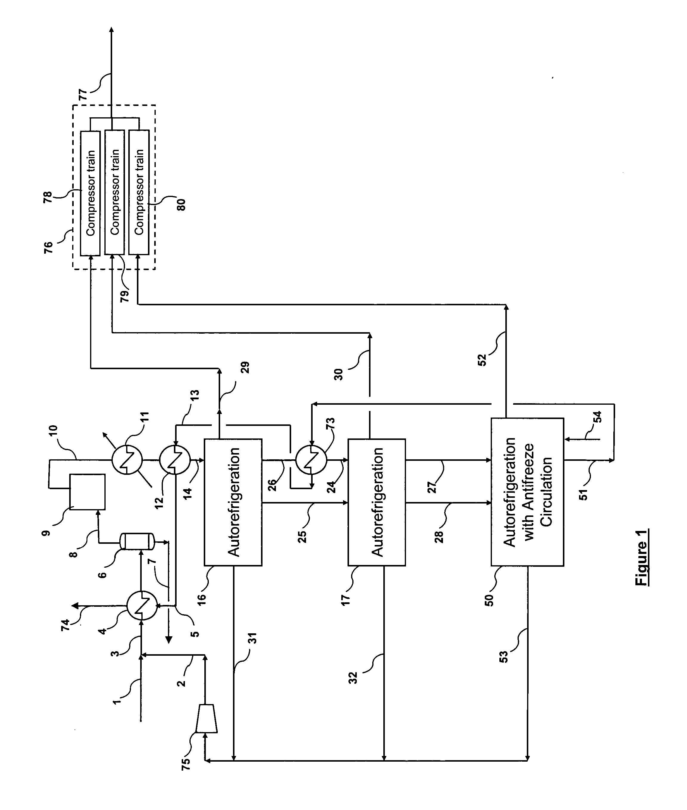
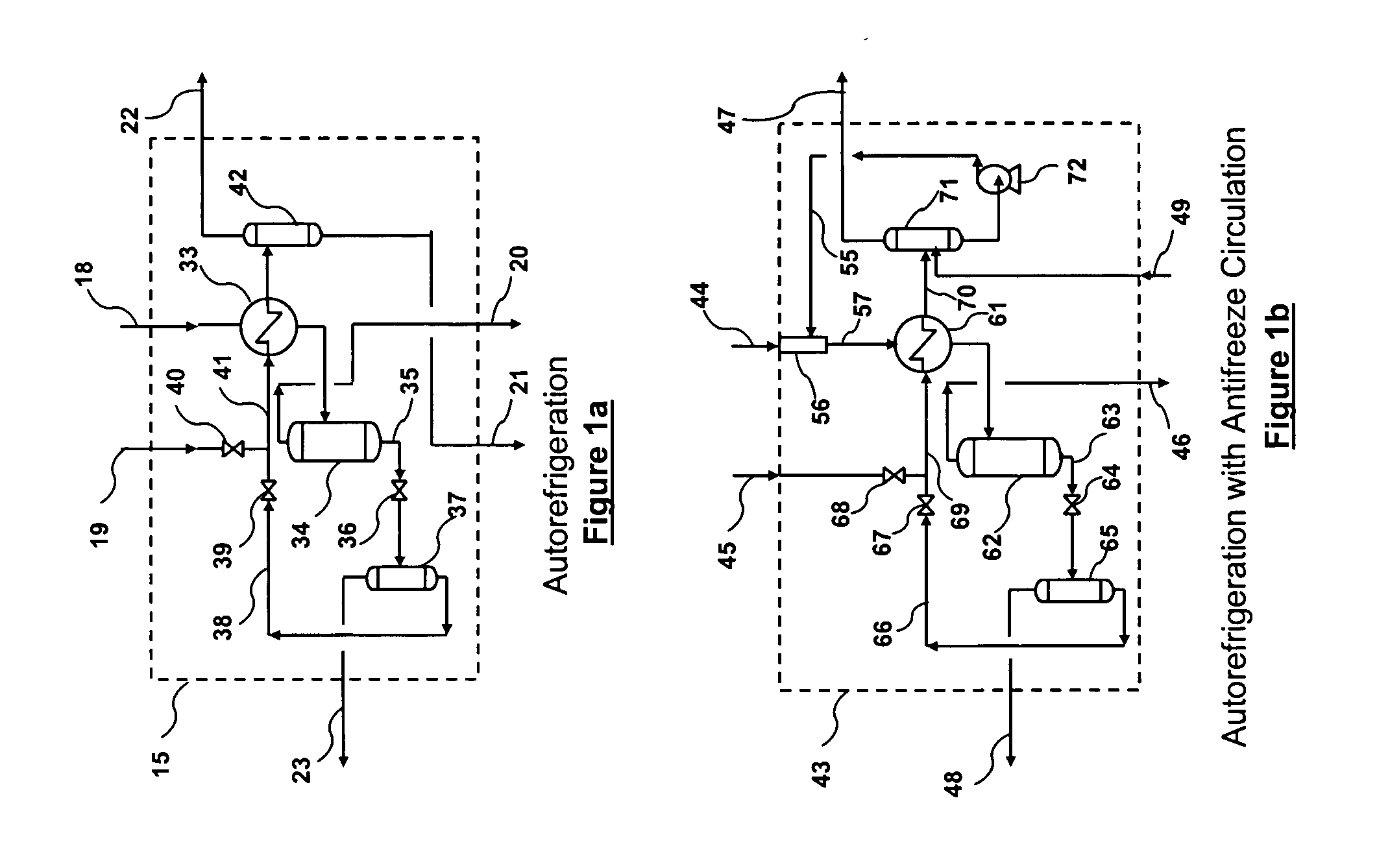
A relatively simple and energy efficient multiple stage cryogenic process for the purification of a hydrogen-rich stream by the removal of acid gases, mainly CO2 and H2S, by method of autorefrigeration and delivering or producing those acid gases, mainly CO2, at pressure sufficiently high for disposal by containment, commonly known as sequestration. Autorefrigeration is comprised of (a) condensing acid gases from the syngas stream by cooling the syngas, (b) separating the liquefied acid gases from the syngas, and (c) evaporating the liquefied acid gases at a pressure lower than that of the syngas to provide cooling. The process is composed of multiple autorefrigeration stages to generate multiple acid gas product streams with a pressure as high as practical in each stream so as to lessen the power needed to pressurize the acid gas streams for sequestration. The final autorefrigeration stage utilizes an antifreeze liquid that allows the final stage to operate below the freezing point of CO2; thus allowing more acid gas removal. The antifreeze liquid is an alcohol or a mixture of alcohols with a freezing point lower than about minus 110 degrees F. and a boiling point higher than about 100 degrees F. The process includes hydrogen recovery and recycle as well as recovery of the energy contained in the sulfur bearing compounds. The process is especially well suited for CO2 removal/sequestration from a coal (or petroleum coke) gasification process.

Description

BACKGROUND OF THE INVENTION [0001] 1. Field of the Invention [0002] This invention relates to the separation of gases. More particularly, it relates to purification of a hydrogen-rich stream by the removal of acid gases, CO2, H2S, and COS, by the method of autorefrigeration. Further, this invention relates to a method for avoiding the emission to the atmosphere of CO2, a so-called greenhouse gas. In a highly preferred embodiment, it relates to the production of CO2 at a pressure sufficiently high for disposal by containment, a method commonly known as sequestration. The sequestration method itself is not a part of this invention. [0003] 2. Description of the Prior Art [0004] There is increasing concern about combustion of fossil fuels worldwide because of the emission of carbon dioxide. Atmospheric CO2 is believed capable of producing a “greenhouse effect” by trapping radiated heat from the earth's surface, thereby contributing to global warming. Although emission of CO2 to the atmo...

Claims


Application Information

Patent Timeline
IPC IPC(8): C10G17/00C07B63/02
CPCC07B63/00C10K1/00F25J3/0625F25J3/0655F25J3/067F25J2210/04Y02C10/12F25J2230/80F25J2235/80F25J2245/02F25J2260/80F25J2270/02F25J2270/90F25J2230/30Y02P20/10Y02P20/129Y02P20/151Y02C20/40
Inventor MCCLANAHAN, TIMMONS S.CRIM, MICHAEL C.
Owner TENNESSEE VALLEY AUTHORITY
Why Eureka
Try Eureka