Magnetically coupled actuator and limit switch assembly for a sealed chamber system

a limit switch and actuator technology, applied in the direction of fluid pressure control, instruments, gearing, etc., can solve the problems of difficult program and configuration, waste of considerable amount of water, etc., and achieve the effect of reducing the power needs of rotating components and high friction seals

Active Publication Date: 2020-09-10
HEANEY JOHN S
View PDF0 Cites 0 Cited by
  • Summary
  • Abstract
  • Description
  • Claims
  • Application Information

AI Technical Summary

Benefits of technology

[0011]Accordingly, it can be seen that the present system provides several unique and novel improvement over systems of the prior art, particularly with respect to sealed chamber magnetic couplers which eliminate the need for high friction seals for rotating parts and which also reduce power needs for rotating components within the sealed chambers.

Problems solved by technology

The existing systems are known to have high power requirements which require wired electrical power, are known to be difficult to program and configure for optimal coverage and are further known to waste considerable amounts of water.

Method used


Image

  • Magnetically coupled actuator and limit switch assembly for a sealed chamber system
  • Magnetically coupled actuator and limit switch assembly for a sealed chamber system
  • Magnetically coupled actuator and limit switch assembly for a sealed chamber system

Examples


Embodiment Construction

[0038]Certain exemplary embodiments will now be described to provide an overall understanding of the principles of the structure, function, manufacture, and use of the device and methods disclosed herein. One or more examples of these embodiments are illustrated in the accompanying drawings. Those skilled in the art will understand that the devices and methods specifically described herein and illustrated in the accompanying drawings are non-limiting exemplary embodiments and that the scope of the present invention is defined solely by the claims. The features illustrated or described in connection with one exemplary embodiment may be combined with the features of other embodiments. Such modifications and variations are intended to be included within the scope of the present disclosure. Further, in the present disclosure, like-numbered components of the embodiments generally have similar features, and thus within a particular embodiment each feature of each like-numbered component i...


PUM


Abstract

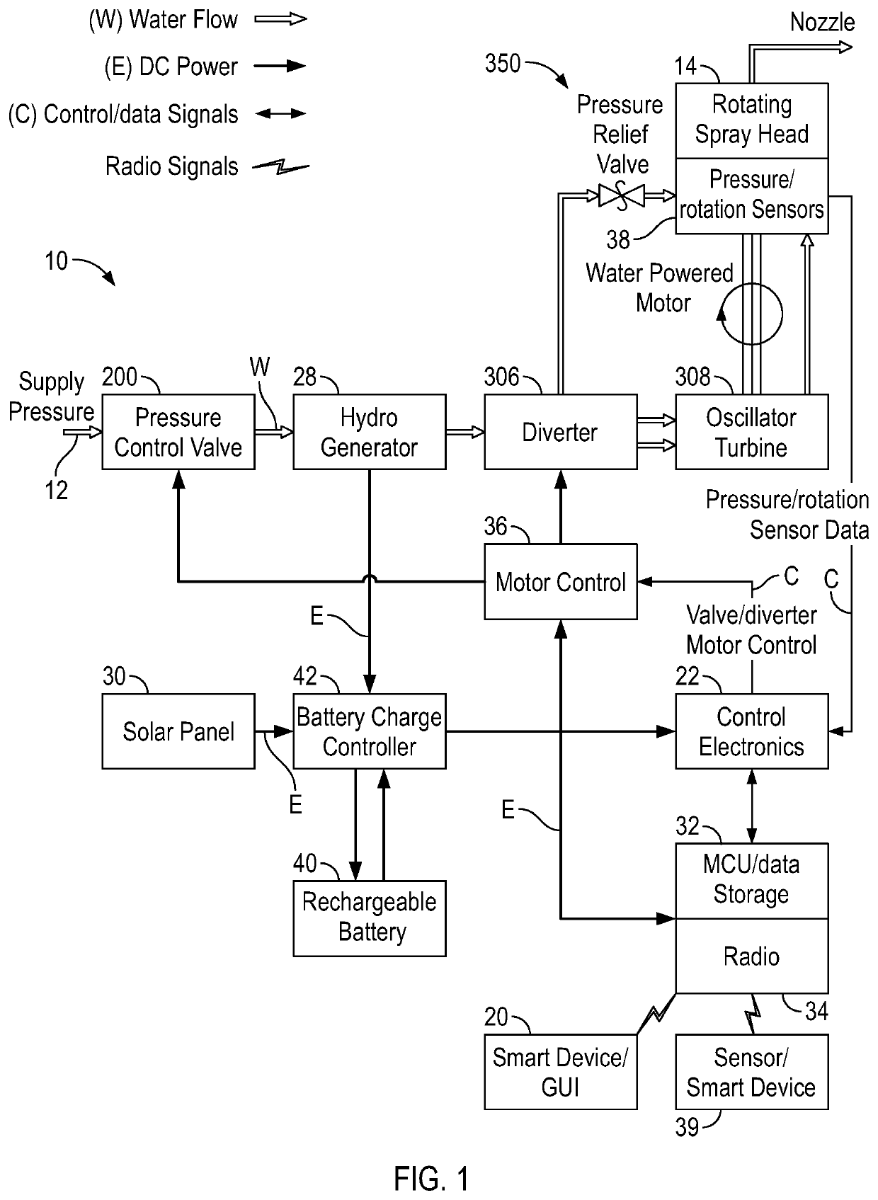
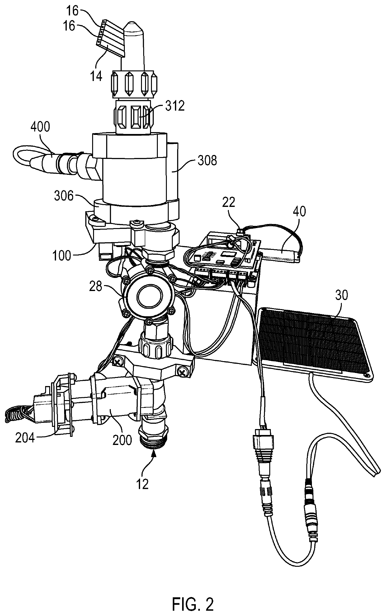
A programmable, electronically controlled sprinkler system has a hermetically sealed internal chamber which encloses all of the internal water flow, valves, mechanical and rotational components and a plurality of magnetic coupling arrangements which allow external motors to control operation of the internal mechanical components without requiring any hydraulic seals.

Description

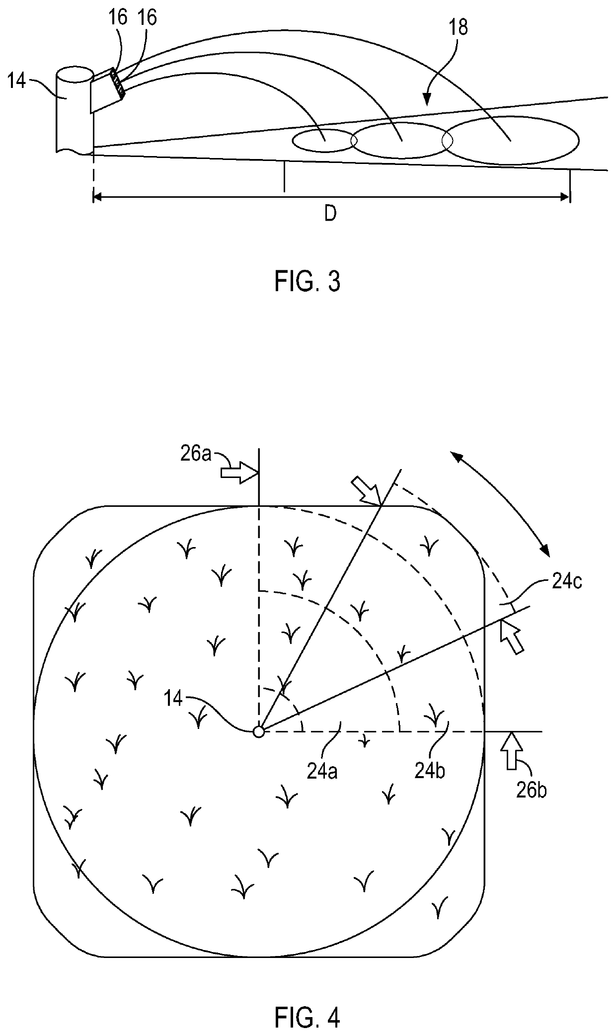
CROSS-REFERENCE TO RELATED APPLICATIONS[0001]The present application claims the benefit of U.S. Provisional Application No. 62 / 815,726, filed Mar. 8, 2019.BACKGROUND OF THE DISCLOSURE[0002]Embodiments of the invention relate to water sprinkler systems, and more particularly to programmable electronically controlled sprinkler systems which are controllable to effect sprinkler direction and time of watering.[0003]The design of present sprinkler systems is focused on structure which allows the water to flow through the system and to mechanically rotate the sprinkler head achieving a predefined of coverage pattern. Electronic controls effect the timing of when the sprinklers are turned on and off. Distance or travel of the spray and rotation arcs of prior art systems are typically controlled mechanically with spray nozzle selection and angle, and mechanical rotational limits.[0004]The existing systems are known to have high power requirements which require wired electrical power, are kn...

Claims


Application Information

Patent Timeline
Patent Type & Authority Applications(United States)
IPC IPC(8): A01G25/16B05B3/04
CPCA01G25/16B05B3/0409A01G25/167B05B3/0436B05B3/0454B05B12/087B05B12/12F16K31/088F16K31/041F16H25/2015F16H2025/2081F16K31/08A01G25/092F16H2025/2071G05D16/202H02K49/108F16K31/04B05B12/16B05B3/0422
Inventor HEANEY, JOHN S.
Owner HEANEY JOHN S
Why Eureka
Try Eureka