Method of transmitting data, electronic device and transponder

a technology of electronic devices and transponders, applied in the near field of read/write/interrogation/identification systems, instruments, indirect connection of subscribers, etc., can solve the problem of relative high power consumption of transponders, and achieve the effect of satisfying performance, reducing the energy consumption of each transponder, and weakening the field

Inactive Publication Date: 2010-04-08
NXP BV
View PDF5 Cites 1 Cited by
  • Summary
  • Abstract
  • Description
  • Claims
  • Application Information

AI Technical Summary

Benefits of technology

[0006]It is an object of the present invention to provide a method of transmitting data between a reader and a transponder, which method is likewise reliable and more power efficient.
[0007]A further object of the invention is to provide an electronic device for a transponder and a transponder which allow a reliable and power efficient communication with a reader.
[0015]Since timing is not as crucial when the transponder receives and decodes signals as it is when generating and sending signals, the inventive method is more power efficient compared to conventional methods, while being at least almost as reliable as conventional methods based on synchronous transfer modes for sending and receiving data.
[0017]In one embodiment of the inventive method, information of a third data stream sent by the reader is written to a memory of the transponder utilizing the internal clock signal. Timing is relatively uncritical when writing data to the transponder memory. So, an asynchronous transfer mode can be used for this operation to save power.
[0022]The inventive electronic device, which may be an integrated circuit, and the inventive transponder comprising the inventive electronic device are thus designed to be used to carry out the inventive method. Since incoming data streams are decoded utilizing the internal clock signal and outgoing data streams are generated and transmitted utilizing the clock information from the reader, the inventive transponder is more power efficient than and at least as reliable as conventional low or high frequency transponders in terms of timing, which conventional transponders clock all signals utilizing a clock information generated by the reader.
[0027]The inventive method or the inventive RFID system may particularly be advantageous if a plurality of inventive transponders are within the radio range of the reader. An example for such a scenario are relatively closely stacked transponders, as it may be the case when labeling and stacking medication. In such a scenario, the individual transponders may affect each other. In order to achieve a satisfactory performance of such an RFID reader transponder system, particularly to identify each transponder reliably, the energy consumption of each transponder should be kept low. If the plurality of transponders are inventive transponders, or at least some or the majority of these transponders are inventive transponders, then only the transponder responding to the reader, i.e. the transponder transmitting the outgoing data stream weakens the field emitted by the reader. During receiving incoming data streams, the inventive transponders do only little, if at all, weaken the field transmitted by the reader, resulting in a reduced power need for the field transmitted by the reader. The reason why the transponders do hardly, if at all, weaken the field transmitted by the reader during receiving data streams is that they decode these data stream utilizing their internal clock signals.

Problems solved by technology

While the synchronous transfer mode allows communication between the transponder and the reader over a relative long distance, it is characterized by a relative high power consumption of the transponder.

Method used


Image

  • Method of transmitting data, electronic device and transponder
  • Method of transmitting data, electronic device and transponder
  • Method of transmitting data, electronic device and transponder

Examples


Embodiment Construction

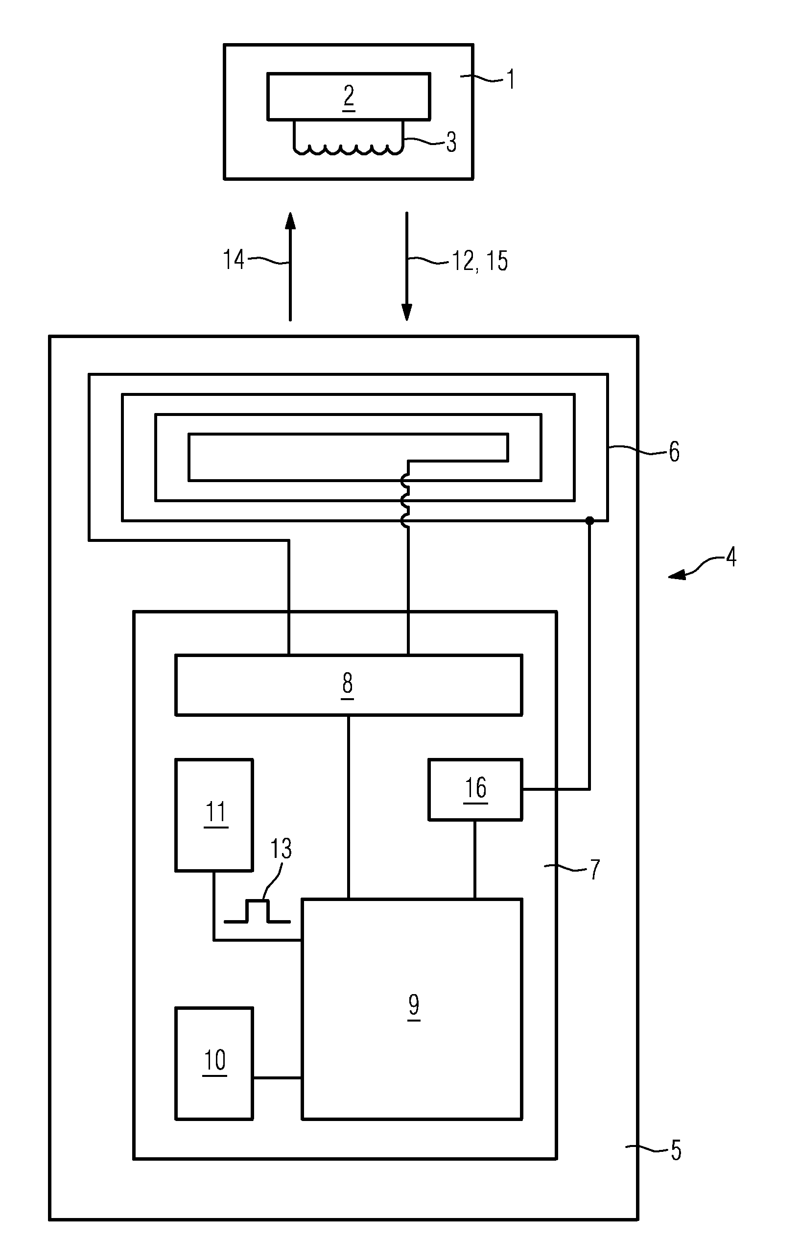
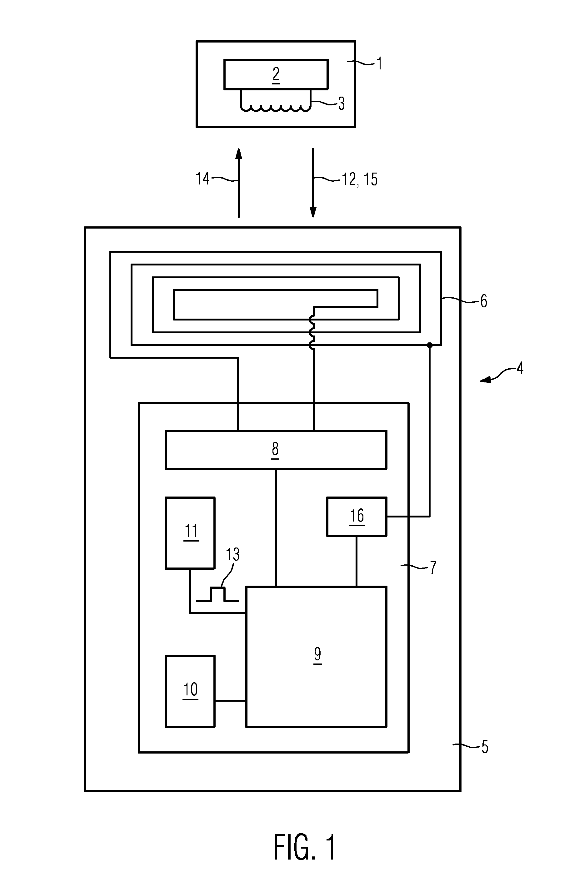
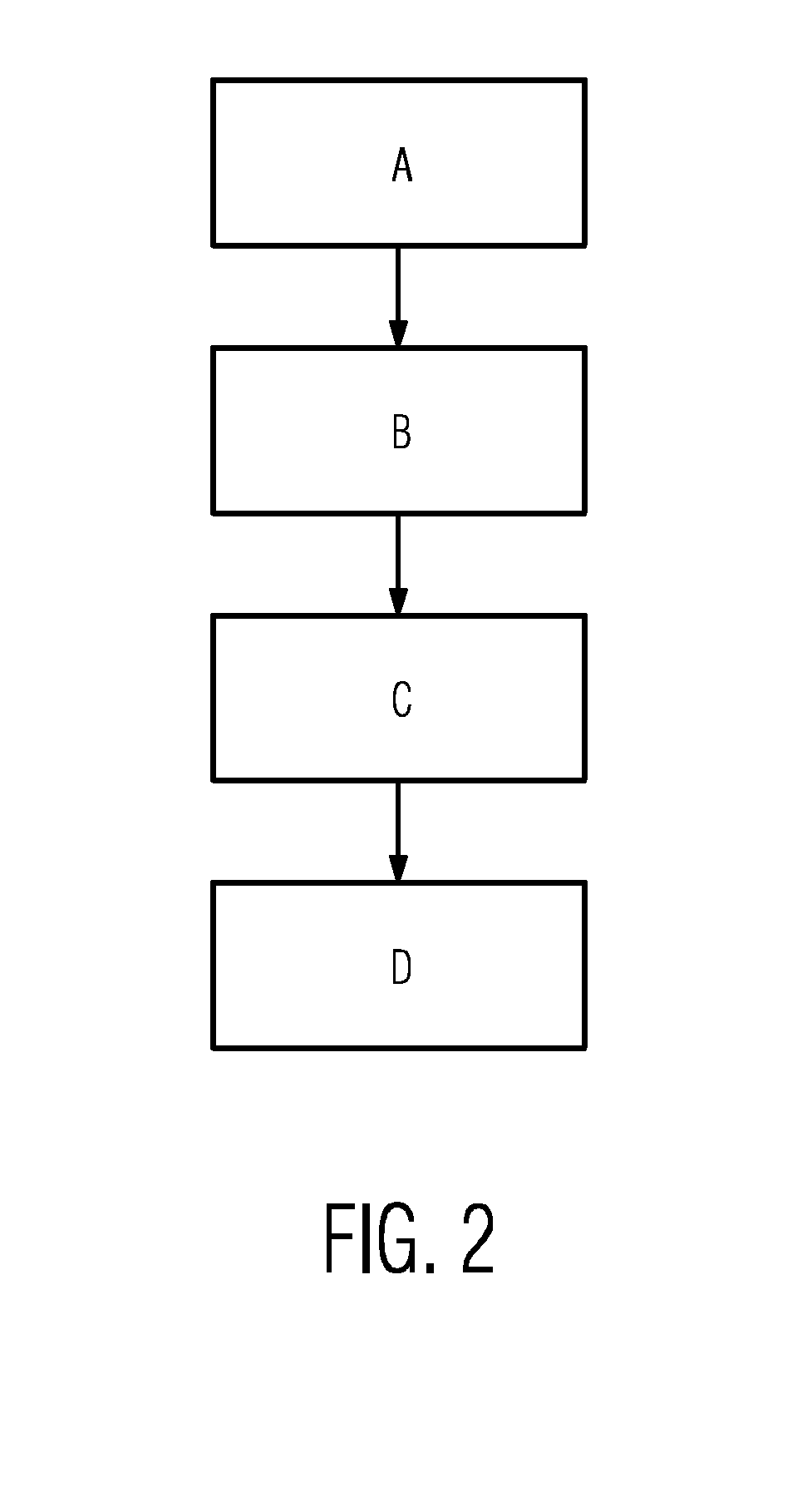
[0031]FIG. 1 shows a reader 1 and a transponder 4 and FIG. 2 shows a flow chart illustrating the operation of the reader 1 transponder 4 system of FIG. 1. In this exemplary embodiment, the transponder 4 operates at low or high frequencies less than 30 MHz, such as 125 kHz or 13.56 MHz.

[0032]In this embodiment, the reader 1 comprises a central processing unit 2 connected to a reader antenna 3. The transponder 4 comprises a substrate 5, a transponder antenna 6 attached to the substrate 5, and an integrated circuit 7 attached to the substrate 5 and connected to the transponder antenna 6. The integrated circuit 7 is an example for an inventive electronic device and comprises a demodulation / modulation stage 8 connected to the transponder antenna 6, a processing device 9 connected to the demodulation / modulation stage 8, a memory 10 for storing data connected to the processing device 9, and an internal clock signal generator 11. The processing device 9 may, for instance, be a microprocesso...


PUM


Abstract

In a method of transmitting data, a low or high frequency transponder (4) receives a first data stream (12) via a field emitted by a reader (1), decodes the first data stream (12) utilizing an internal clock signal (13) generated by the transponder (4), and generates and emits a second data stream (14) to the reader (1) in response to the first data stream (12). The second data stream (14) is generated and transmitted utilizing a clock information transmitted via the field emitted by the reader (1).

Description

FIELD OF THE INVENTION[0001]The invention relates to a method of transmitting data, to an electronic device, and to a transponder.BACKGROUND OF THE INVENTION[0002]Transponders, which are also referred to as tags or labels, are well known in the art and are designed to communicate with a reader, which is also known as a base station. Usually, the transponder comprises an electronic circuit, for instance, an integrated circuit and an antenna to capture signals sent by the reader. Then, the electronic circuit processes the signals captured by the antenna and may generate a response signal for the reader.[0003]Conventional low and high frequency transponder reader systems are designed such that the information transfer between the reader and the transponder and between the transponder and the reader is based on a synchronous data transfer, meaning that the electronic circuit of the transponder and thus the signal processing carried out by the electronic circuit is based on a clock infor...

Claims


Application Information

Patent Timeline
Patent Type & Authority Applications(United States)
IPC IPC(8): H04Q5/22
CPCH04B5/0056G06K7/10198G06K7/0008H04B5/0068H04B5/45H04B5/77
Inventor AMTMANN, FRANZ
Owner NXP BV
Why Eureka
Try Eureka