Extended continuous passive shimming of magnets

a magnetic field and passive shimming technology, applied in the field of methods and apparatuses for homogenizing or correcting the magnetic field of magnets, can solve the problems of creating spurious “highs” and achieve the effects of weak fields, less space, and less spa

Active Publication Date: 2020-08-11
NUEVOMR LLC
View PDF18 Cites 1 Cited by
  • Summary
  • Abstract
  • Description
  • Claims
  • Application Information

AI Technical Summary

Benefits of technology

[0009]The presently disclosed apparatus and method combines the advantageous features of both non-mechanical and mechanical methods for field correction. There are disclosed herein innovative designs, materials, and production methods for passive shims. As disclosed herein, the passive shims are produced in a way that creates correction fields that can have nearly continuously-valued field strength, so that errors in the original field can be corrected with high fidelity. Further, as disclosed herein, the passive shims are designed and constructed in a manner that utilizes spatially extended structures in lieu of buttons, which reduces the creation of spurious “high-order” fields (fields that vary rapidly with respect to spatial location), which are a common problem with existing passive shimming technologies. The materials and methods disclosed herein also are advantageous in that they may be very thin and thereby preserve the working space inside the magnets. This may allow the passive shimming of magnets that are too small to be passively shimmed by conventional methods and materials.
[0011]The passive shim systems and processes disclosed herein combine the best properties of active and passive shimming approaches. Like traditional passive shims, the present systems can be used without the need for sources of electrical current or other “active” apparatus, so that the inventive methods and apparatus can require no power and the overall device containing the magnet does not require high-precision active shim control apparatus, which may be complicated or bulky. Like traditional active shims, the present system and method can create fields of a strength that may be selected from a continuous or nearly continuous set of values, so that the correction field may be well-matched to any desired field correction. The present apparatus and method has advantages over existing button shimming techniques, in that it uses spatially extended structures rather than discrete, localized buttons.
[0012]The linear extent of the spatial structures of the methods and system disclosed here is typically larger than the linear size of the volume of space over which the correction is to be achieved. This reduces or eliminates the production of high-order error fields (fields that vary rapidly as a function of spatial location) that are present when the source of the correction field is a localized point source (e.g., the buttons). The methods disclosed herein also are preferred over traditional passive shim production methods in that the new methods are extremely fast and easily automated. This reduces the expense of production, enables rapid prototyping and iterative correction, and may also reduce the need for sophisticated computation of magnetic fields. The ease of production may also enable the adjustment or repair of magnets in the field, after they have been sited away from the magnet production facility. Ease of passive shim production may also allow for rapid adaptation of the same fundamental methods to new circumstances. As disclosed herein, the passive shims may be produced using readily available, ordinary materials and tools, further reducing costs when compared to traditional passive shimming methods. The ability to design and produce the herein disclosed passive shims rapidly can eliminate the need for accurate calculations of magnetic fields produced by passive shim buttons. This is advantageous when correcting the field of magnets with pole pieces, as the accuracy of these calculations is often not high enough to achieve very high precision corrections, due to the interfering effects of pole magnetization response (e.g., image currents, etc.), as is known in the art.
[0014]The shims disclosed herein also offer particular advantages for the correction of small magnets, those with a gap between their poles of 20 mm or less, as well as magnets of any size in which the space available for the passive shim structure is limited. The materials used, for example in the preferred embodiment, are extremely thin (typically less than 0.5 mm in thickness, and often much thinner). Hence, these shims can be installed in magnets without compromising the space available for other elements of the apparatus, whereas traditional buttons, being discrete pieces of material that are handled individually, typically required more space. An additional advantage is that the shim materials and production methods disclosed here can produce shims with very weak fields. For small magnets, traditional buttons (which have a minimum size and must be placed close to the region of space in which the field correction is being carried out) create fields that are much stronger than desired, leading to severe demands on controlling their locations and placing an unattainably high requirement for accuracy in the field calculations used to design the traditional button shim layout.

Problems solved by technology

Further, as disclosed herein, the passive shims are designed and constructed in a manner that utilizes spatially extended structures in lieu of buttons, which reduces the creation of spurious “high-order” fields (fields that vary rapidly with respect to spatial location), which are a common problem with existing passive shimming technologies.

Method used


Image

  • Extended continuous passive shimming of magnets
  • Extended continuous passive shimming of magnets
  • Extended continuous passive shimming of magnets

Examples


Embodiment Construction

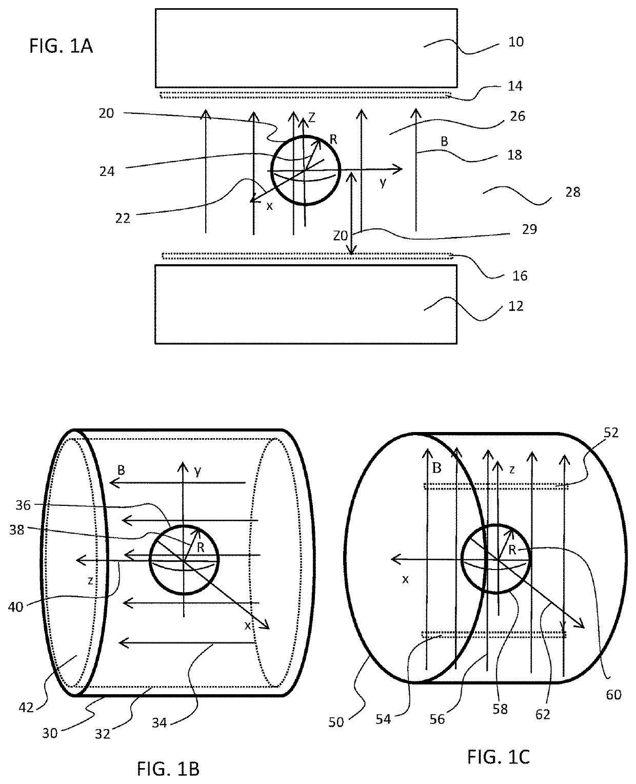
[0030]To understand the concepts and methods disclosed herein, it is helpful to consider some geometrical definitions. FIG. 1 shows some typical magnet geometries and associated mathematical coordinate systems and volumes of space over which the magnetic field is to be corrected. FIG. 1A shows a typical dipole magnet, which is a common format for magnets built with electromagnetic or permanent magnet technologies. This configuration has a north magnetic pole 10 and a south magnetic pole 12 that define two parallel surfaces facing each other across a gap. The poles are often circular or axially symmetric in general shape; in FIG. 1A they are shown from the side. The magnetic field B 18 points from one pole to the other and is nominally uniform throughout the gap. The coordinate system 22 for this type of magnet is conveniently positioned with its origin at the geometrical center of the gap space and its Z-axis lying along the direction of the magnetic field. The direction of the X an...


PUM


Abstract

Methods and apparatuses for homogenizing or correcting the magnetic fields of magnets, particularly the magnetic fields employed in nuclear magnetic resonance (NMR) and magnetic resonance imaging (MRI) applications. There are disclosed passive shims for making such homogenizations or corrections, methods for making such shims, and a method and apparatus for creating desirable correction fields in which the correction field strength has limited harmonic content, near continuous value of field strength, and occupies minimal space in the magnet.

Description

CROSS REFERENCE TO RELATED APPLICATION[0001]This application claims the benefit of, and priority to, U.S. Provisional Patent Application Ser. No. 62 / 324,227 filed 18 Apr. 2016, entitled “Extended Continuous Passive Shimming of Magnets,” and the entire disclosure thereof is incorporated herein by reference.FIELD OF THE INVENTION[0002]This invention relates generally to methods and apparatuses for homogenizing or correcting the magnetic fields of magnets, particularly the magnetic fields employed in nuclear magnetic resonance (NMR) and magnetic resonance imaging (MRI) applications, and more particularly to passive shims for making such homogenizations or corrections, and specifically to a method and apparatus for creating desirable correction fields in which the correction field strength has limited harmonic content, near continuous value of field strength, and occupies minimal space in the magnet.BACKGROUND OF THE INVENTION[0003]Strong, uniform magnetic fields are desirable in many s...

Claims


Application Information

Patent Timeline
Patent Type & Authority Patents(United States)
IPC IPC(8): G01R33/3873G01R33/38
CPCG01R33/3802G01R33/3873G01R33/3806
Inventor MCDOWELL, ANDREW F.
Owner NUEVOMR LLC
Why Eureka
Try Eureka