High-energy eye-safe pulsed fiber amplifiers and sources operating in erbium's L-band

a pulsed fiber amplifier, high-energy technology, applied in the direction of fibre transmission, laser details, electrical equipment, etc., to achieve the effect of increasing energy extraction

Inactive Publication Date: 2011-01-18
LOCKHEED MARTIN CORP
View PDF15 Cites 161 Cited by
  • Summary
  • Abstract
  • Description
  • Claims
  • Application Information

AI Technical Summary

Benefits of technology

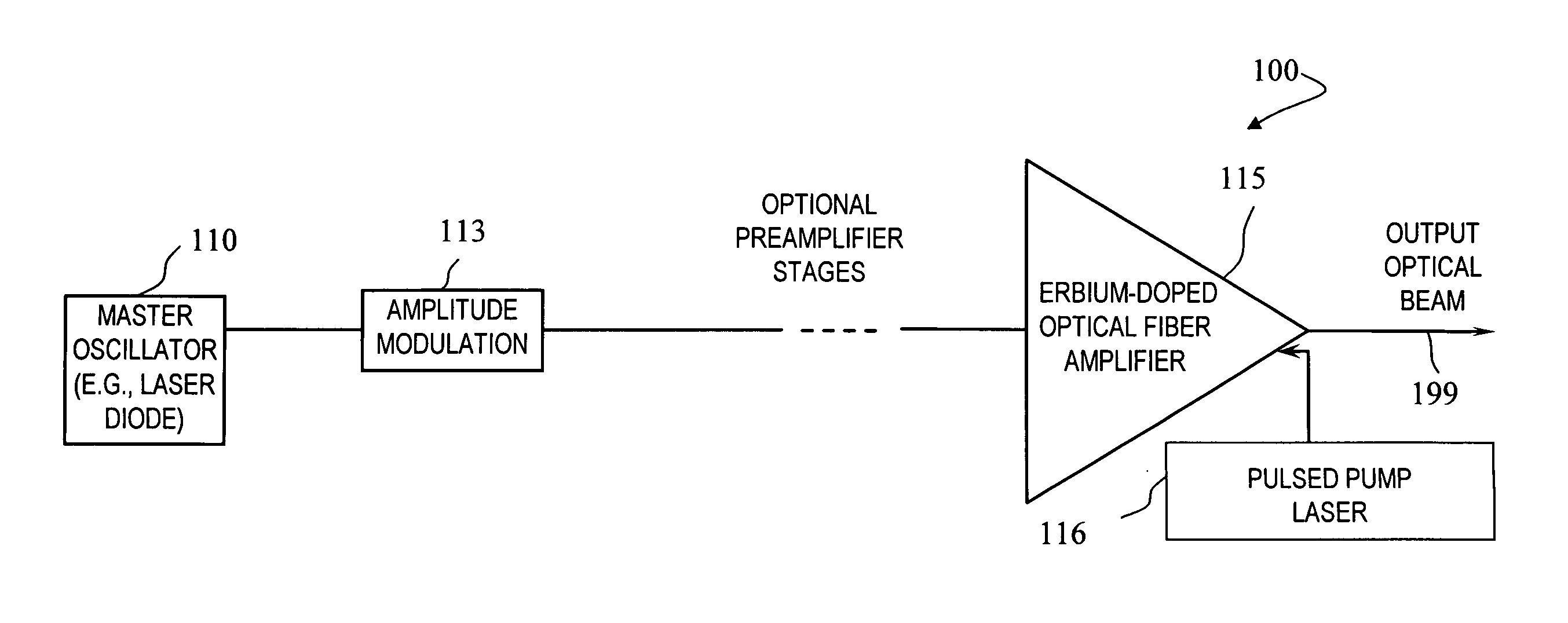
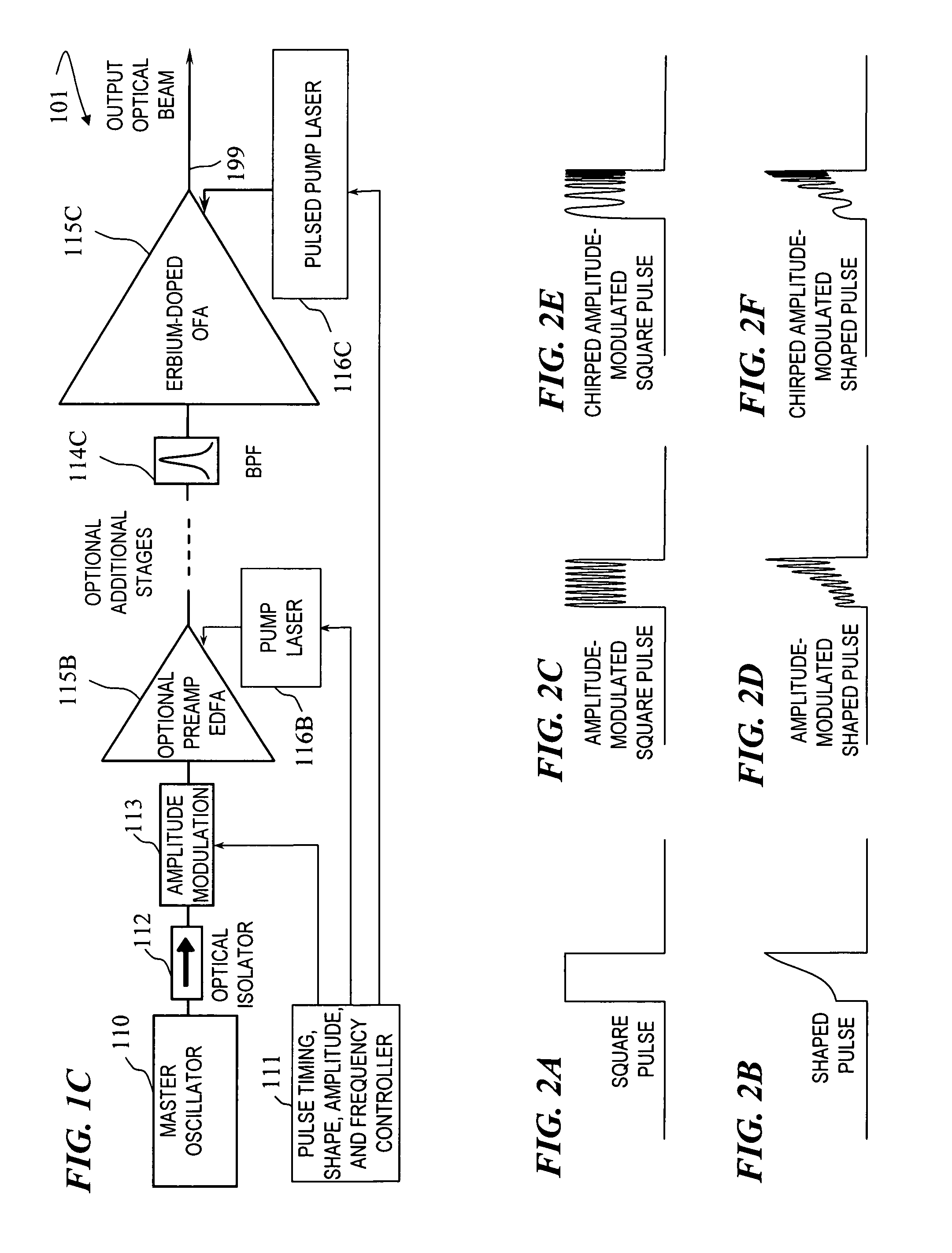
[0013]In some embodiments, the systems of the present invention are capable of, and do, deliver high energy, (up to and exceeding 20 mJ), long bursts (10-40 microseconds (μs)), of chirped amplitude-modulated radiation (wherein the chirp includes 10 MHz-800 MHz modulation frequencies; i.e., the chirp in one “pulse” starts at 10 MHz and changes frequency in a continuous manner up to 800 MHz) at eye-safe wavelengths in erbium's L-band (e.g., using wavelengths in the range of about 1550 nm to about 1630 nm) with good beam quality (M2<2.8). In some embodiments, a ytterbium-free (Yb-free) double-clad large-mode-area (LMA) erbium fiber in an amplifier configuration operating in the L-band and in particular the far L-band (e.g., some such embodiments operate at a signal wavelength of 1590 nm) is used to enhance the efficiency and energy storage of the fiber optical amplifier. By employing pulse pumping (i.e., providing optical pump light into the fiber amplifier only while extracting power, which can be considered quasi-cw operation depending on the pulse length) the output energy per pulse is increased. Pulse pumping also minimizes ASE and transient-induced Q-switching at low pulse-repetition-rate (rep-rate) operation. Further, by advancing or delaying the start of the extraction pulse relative to the start of the pump pulse by a few micro-seconds (e.g., starting the pump pulse 1 to 10 microseconds before or after the start of the signal pulse, the amount and direction of which are easily determined empirically, such as shown in FIG. 12A-FIG. 12D), pulse steepening (early pulse overshoot / distortion due to stored pump power that increases the amount of gain early in the signal pulse) is minimized or removed, and signal amplification is achieved with excellent fidelity (e.g., the amount of gain remains substantially constant for the duration of the signal pulse).
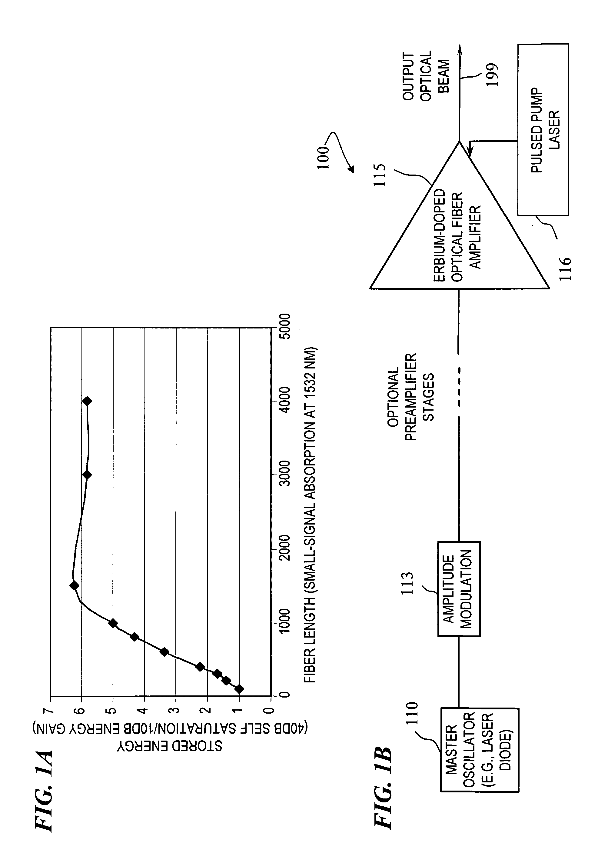
[0015]Even in the nanosecond-pulse-length (ns-pulse-length) regime, higher energies (measured in joules) can be extracted by designing the system judiciously around an L-band wavelength. In a cladding-pumped system, the clustering losses associated with very high concentrations of an active dopant (e.g., erbium) are mitigated by both the cladding pumping scheme and the off-peak signal wavelength. Hence high-dopant-concentration fibers, conventionally ruled out on efficiency grounds for C-band operation, may compensate for the longer lengths of gain fibers (or relative length in terms of erbium ions) required in L-band amplifiers.
[0016]Yb-free fibers based on an alumino-silicate host therefore become the preferred approach for some embodiments of the present invention. While cladding pumping of the C-band signal wavelengths is facilitated by the Yb co-doping in conventional fiber amplifiers, in some embodiments of the present invention, L-band efficiency and energy storage actually benefit from the weak pump rate associated with double-clad fibers. The main benefits, in some embodiments, are inversion flattening and mitigation of clustering-induced pump losses.

Problems solved by technology

If the pump light is applied before the arrival of the signal light, the amount of inversion (i.e., stored power) can build up such that when the signal is launched into the amplifying fiber, the initial portion of the signal pulse is amplified to a greater extent (called “overshoot” which is undesirable for many applications) than are the middle and later portions of the signal pulse.

Method used


Image

  • High-energy eye-safe pulsed fiber amplifiers and sources operating in erbium's L-band
  • High-energy eye-safe pulsed fiber amplifiers and sources operating in erbium's L-band
  • High-energy eye-safe pulsed fiber amplifiers and sources operating in erbium's L-band

Examples


Embodiment Construction

[0062]Although the following detailed description contains many specifics for the purpose of illustration, a person of ordinary skill in the art will appreciate that many variations and alterations to the following details are within the scope of the invention. Accordingly, the following preferred embodiments of the invention is set forth without any loss of generality to, and without imposing limitations upon the claimed invention.

[0063]In the following detailed description of the preferred embodiments, reference is made to the accompanying drawings that form a part hereof, and in which are shown by way of illustration specific embodiments in which the invention may be practiced. It is understood that other embodiments may be utilized and structural changes may be made without departing from the scope of the present invention.

[0064]The leading digit(s) of reference numbers appearing in the Figures generally corresponds to the Figure number in which that component is first introduce...


PUM


Abstract

An apparatus and that provide an optical-fiber amplifier having at least one erbium-doped fiber section and an optical pump coupled to the erbium-doped fiber section, wherein the apparatus is operable to amplify signal pulses to high energy in the erbium-doped fiber section, the pulses having a wavelength in the range of about 1565 nm to about 1630 nm. In some embodiments, the amplifying fiber is ytterbium free.

Description

CROSS-REFERENCE TO RELATED APPLICATIONS[0001]This application claims benefit of U.S. Provisional Patent Application No. 60 / 885,916 filed on Jan. 21, 2007, titled “HIGH-ENERGY EYE-SAFE PULSED FIBER AMPLIFIERS AND SOURCES OPERATING IN L-BAND,” which is incorporated herein by reference in its entirety.[0002]This application is related to commonly owned U.S. patent application Ser. No. 11 / 165,676 (now U.S. Pat. No. 7,792,166) titled “APPARATUS AND METHOD FOR DRIVING LASER DIODES” by Lawrence A. Borschowa; U.S. Pat. No. 7,260,299 to Fabio Di Teodoro et al., titled “MULTI-SEGMENT PHOTONIC-CRYSTAL-ROD WAVEGUIDES COUPLED ACROSS A FREE-SPACE GAP AND ASSOCIATED METHOD” that issued Aug. 21, 2007; U.S. patent application Ser. No. 11 / 567,740 (now U.S. Pat. No. 7,590,856) titled “APPARATUS AND METHOD FOR AN ERBIUM-DOPED FIBER FOR HIGH-PEAK-POWER APPLICATIONS” by John D. Minelly et al.; and U.S. patent application Ser. No. 11 / 556,658 (now U.S. Pat. No. 7,400,807) titled “APPARATUS AND METHOD FOR A...

Claims


Application Information

Patent Timeline
Patent Type & Authority Patents(United States)
IPC IPC(8): H04B10/17
CPCH01S3/06758H04B10/291H01S3/0085H01S3/06729H01S3/0677H01S3/094003H01S3/094007H01S3/094076H01S3/10007H01S3/10015H01S3/1608H01S3/1001H01S3/1003H01S3/06766H01S2301/02
Inventor MINELLY, JOHN D.ALTERMAN, DEBORAH A.
Owner LOCKHEED MARTIN CORP
Why Eureka
Try Eureka