Methods of fabricating a semiconductor device

Active Publication Date: 2007-01-25
SAMSUNG ELECTRONICS CO LTD
View PDF1 Cites 158 Cited by
  • Summary
  • Abstract
  • Description
  • Claims
  • Application Information

AI Technical Summary

Benefits of technology

[0033] According to example embodiments of the present invention, the occurrence of pattern failures due to a bridge phenomenon and/or a pitting phenomenon between adjacent patterns may be retarded, or prevent

Problems solved by technology

With a design rule of a device decreasing resolution of a photolithography process, which may be used to form the pattern of a semiconductor device capable of meeting certain requirements, may be limited.
The formation of a pattern having a finer pitch may also be limited.
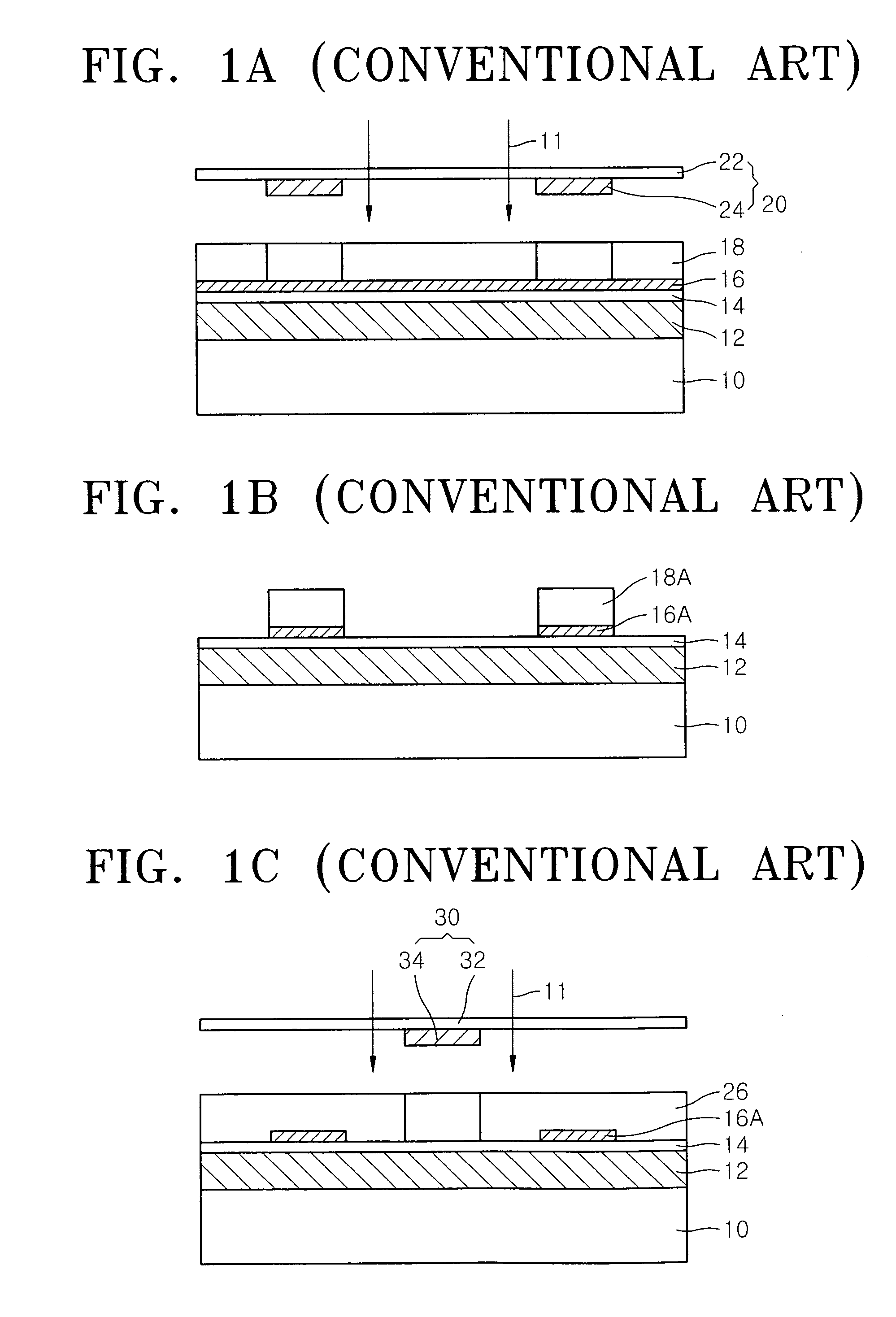
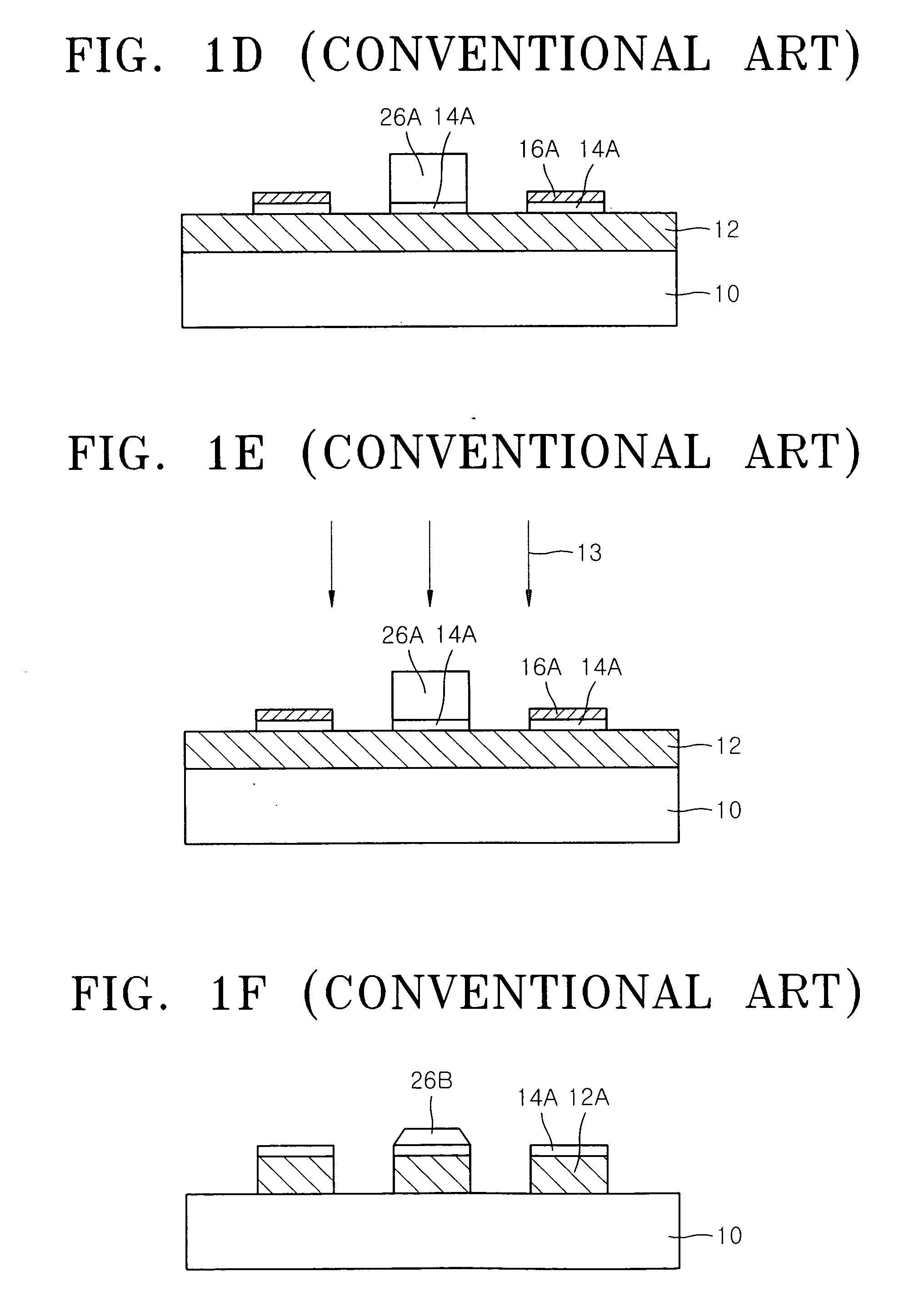
The conventional method of forming a pattern as described above is limited in the formation of a fi

Method used


Image

  • Methods of fabricating a semiconductor device
  • Methods of fabricating a semiconductor device
  • Methods of fabricating a semiconductor device

Examples


Embodiment Construction

[0043] Various example embodiments of the present invention will now be described more fully with reference to the accompanying drawings in which some example embodiments of the invention are shown. In the drawings, the thicknesses of layers and regions may be exaggerated for clarity.

[0044] Detailed illustrative embodiments of the present invention are disclosed herein. However, specific structural and functional details disclosed herein are merely representative for purposes of describing example embodiments of the present invention. This invention may, however, may be embodied in many alternate forms and should not be construed as limited to only the embodiments set forth herein.

[0045] Accordingly, while example embodiments of the invention are capable of various modifications and alternative forms, embodiments thereof are shown by way of example in the drawings and will herein be described in detail. It should be understood, however, that there is no intent to limit example emb...


PUM

PropertyMeasurementUnit
Temperatureaaaaaaaaaa
Thicknessaaaaaaaaaa
Viscosityaaaaaaaaaa

Abstract

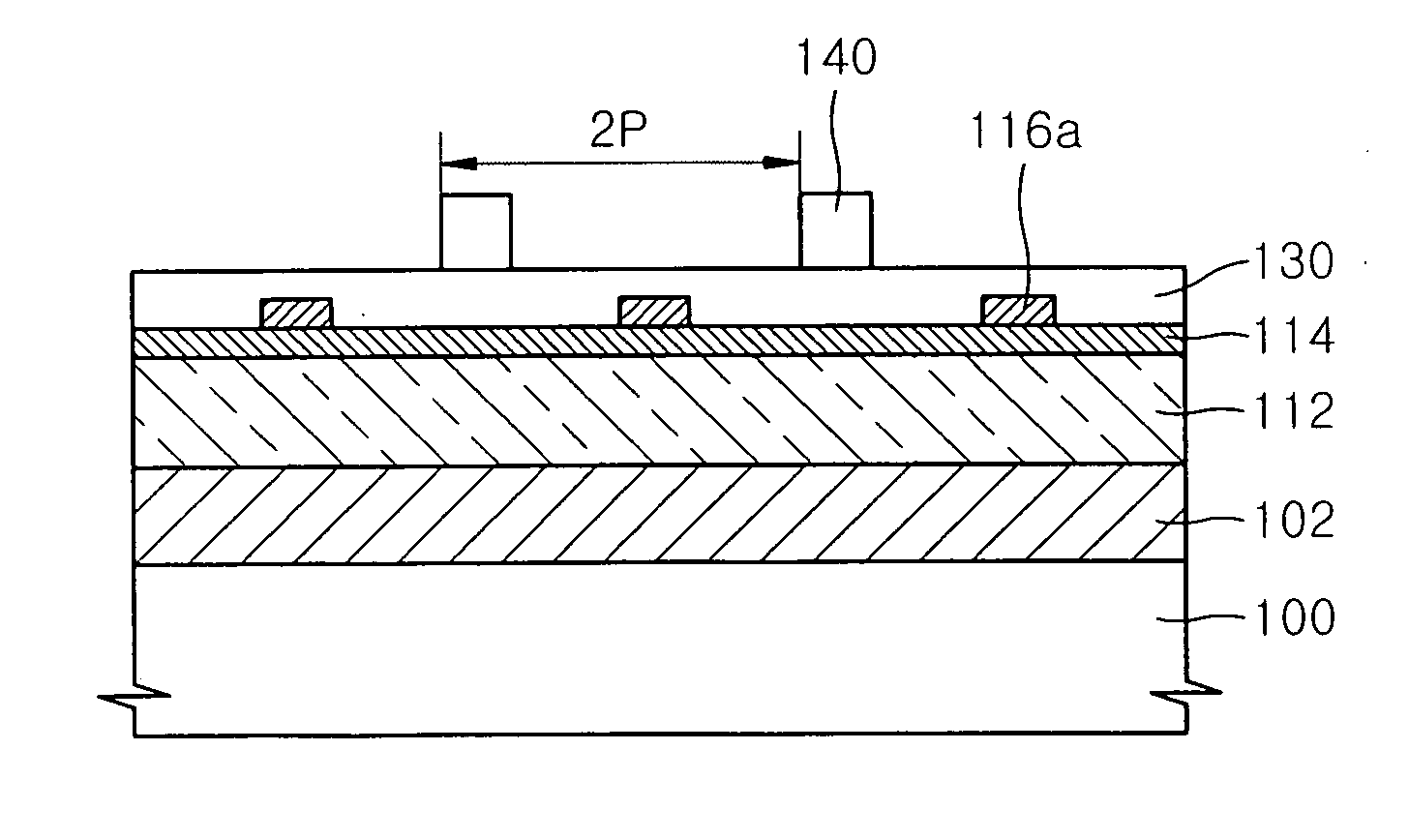
Methods of fabricating a semiconductor device are provided. Methods of forming a finer pattern of a semiconductor device using a buffer layer for retarding, or preventing, bridge formation between patterns in the formation of a finer pattern below resolution limits of a photolithography process by double patterning are also provided. A first hard mask layer and/or a second hard mask layer may be formed on a layer of a substrate to be etched. A first etch mask pattern of a first pitch may be formed on the second hard mask layer. After a buffer layer is formed on the overall surface of the substrate, a second etch mask pattern of a second pitch may be formed thereon in a region between the first etch mask pattern. The buffer layer may be anisotropically etched using the second etch mask pattern as an etch mask, forming a buffer layer pattern. The second hard mask layer may be anisotropically etched using the first etch mask pattern and/or the buffer layer pattern as etch masks, forming a second hard mask pattern. The first hard mask layer may be anisotropically etched using the second hard mask pattern as an etch mask, forming a first hard mask pattern. The etched layer may be anisotropically etched using the first hard mask pattern as an etch mask.

Description

PRIORITY STATEMENT [0001] This application claims benefit of priority under 35 USC §119 from Korean Patent Application No. 10-2005-0067292, filed on Jul. 25, 2005, in the Korean Intellectual Property Office, the contents of which are incorporated herein by reference in its entirety. BACKGROUND OF THE INVENTION [0002] 1. Field of the Invention [0003] Example embodiments of the present invention relates to methods of fabricating a semiconductor device. Other example embodiments relate to methods of forming a finer pattern of a semiconductor device using a double patterning technique. [0004] 2. Description of the Related Art [0005] Miniaturization of a pattern in semiconductor fabrication may be necessary for higher integration of a semiconductor device. In order to integrate more elements in a narrower area, the size of a discrete element may be reduced. Pitch, which is the sum of a width and a distance of a desired pattern, may be reduced. With a design rule of a device decreasing re...

Claims


Application Information

Patent Timeline
IPC IPC(8): G03F7/26
CPCG03F7/0035G03F7/40H01L21/32139H01L21/0338H01L21/0337H01L21/027
Inventor KOH, CHA-WONWOO, SANG-GYUNNAM, JEONG-LIMCHI, KYEONG-KOOOH, SEOK-HWANYEO, GI-SUNGCHUNG, SEUNG-PILPARK, HEUNG-SIK
Owner SAMSUNG ELECTRONICS CO LTD
Why Eureka
Try Eureka