Centrifugal pump unit

Active Publication Date: 2011-03-31
GRUNDFOS MANAGEMENT AS
View PDF9 Cites 2 Cited by
  • Summary
  • Abstract
  • Description
  • Claims
  • Application Information

AI Technical Summary

Benefits of technology

[0004]It is therefore the object of the invention to provide an improved centrifugal pump assembly which permits

Problems solved by technology

Given the same frequency of the output voltage of the frequency converter, one may fu

Method used


Image

  • Centrifugal pump unit
  • Centrifugal pump unit
  • Centrifugal pump unit

Examples


Embodiment Construction

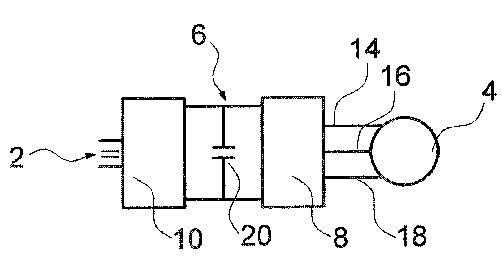
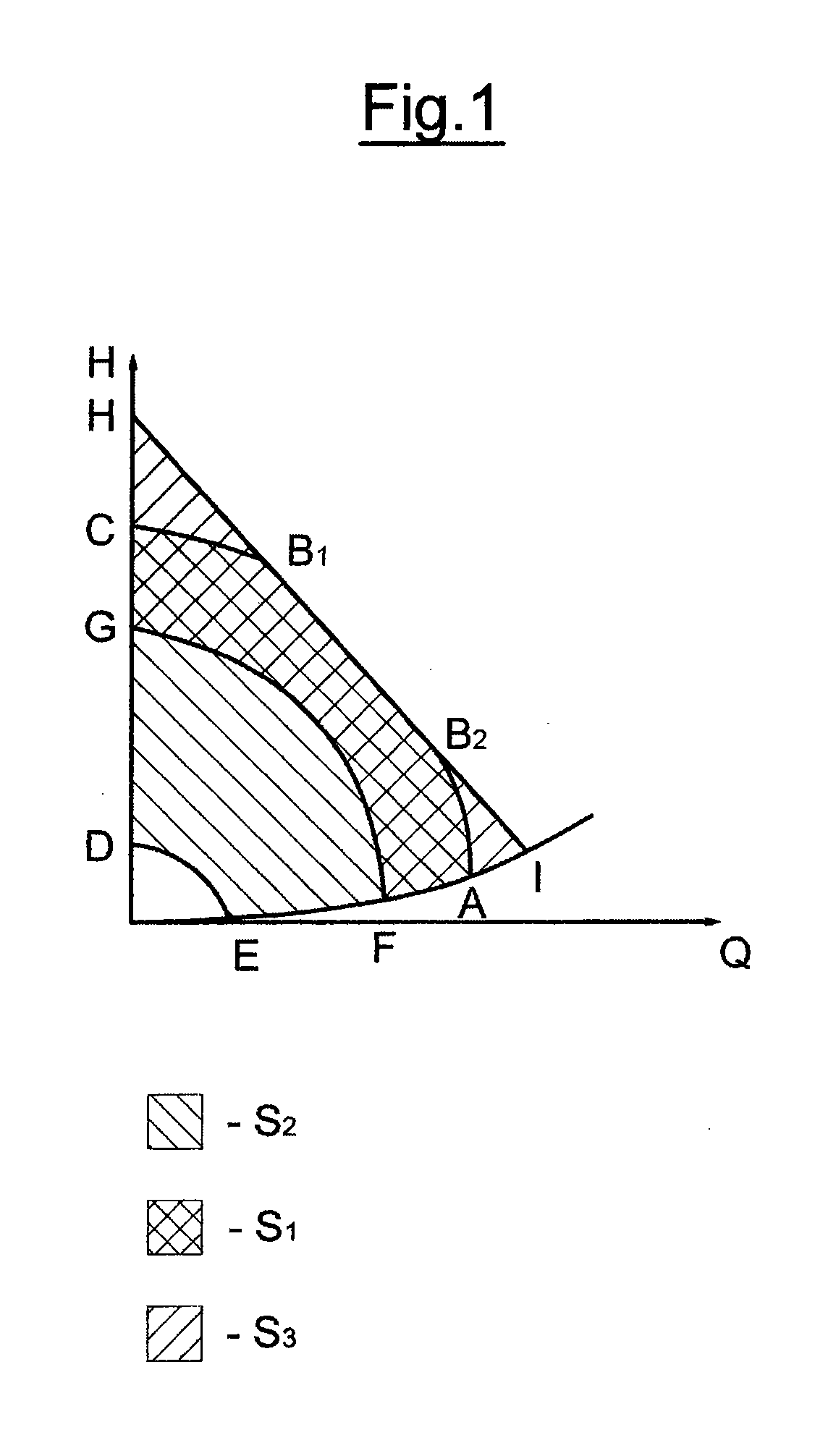
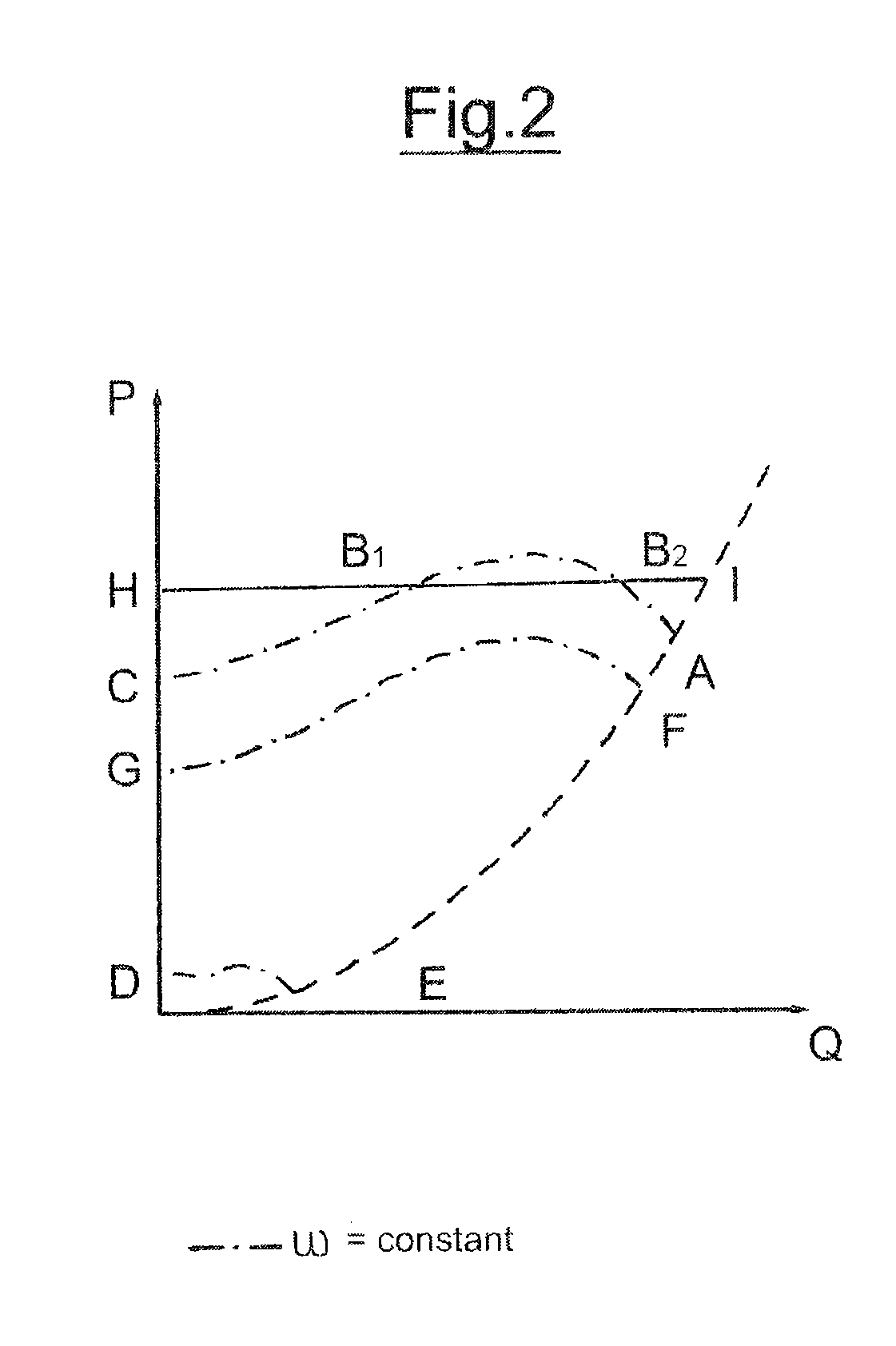
[0031]The basic control and regulation regions of a centrifugal pump assembly according to the invention is explained by way of FIGS. 1 and 2. Thereby, FIG. 1 shows an HQ (pressure-throughput) diagram of a centrifugal pump assembly according to the invention, and FIG. 2 a PQ (power-throughput) diagram. Thereby, P is the electrical input power. The dot-dashed lines in FIG. 2 show the curves of a constant rotational speed ωkonst. With a normal control of the drive motor by way of a frequency converter, the operating field of the pump assembly in the HQ-diagram would be limited by the line CB1B2A. This is the line of maximum rotational speed in the regions CB1 and B2A. The characteristic field between B1 and B2 is limited by the maximum electrical connection power, as may be recognized in FIG. 2. The maximum rotational speed with a conventional control is limited by the maximum exit voltage as well as the maximum make-to-break ratio of the frequency converter. Conventionally, the regul...


PUM


Abstract

The invention relates to a centrifugal pump assembly with an electric drive motor and with a control device having a frequency converter, for the control of the rotational speed of the drive motor, wherein the control device is designed in a manner such that in at least one control region, a field weakening is produced in the drive motor, by way of which the rotational speed of the drive motor is increased.

Description

CROSS-REFERENCE TO RELATED APPLICATIONS[0001]This application is a section 371 of International Application No. PCT / EP2009 / 003284, filed May 8, 2009, which was published in the German language on Dec. 17, 2009 under International Publication No. WO 2009 / 149796 A3, the disclosure of which is incorporated herein by reference.BACKGROUND OF THE INVENTION[0002]The invention relates to a centrifugal pump assembly with an electric drive motor and with a control device having a frequency converter, for controlling the rotational speed of the drive motor.[0003]Centrifugal pump assemblies are known, with which the electrical drive motor is activated by way of a frequency converter, in order to be able to vary the rotational speed of the drive motor and thus of the centrifugal pump assembly. Thereby, it is very desirable to be able to operate the pump assembly with the greatest possible efficiency. The maximum hydraulic power which is available, with known centrifugal pump assemblies, is limit...

Claims


Application Information

Patent Timeline
IPC IPC(8): F04B49/06F04B35/04
CPCF04D13/06H02P21/0089H02P21/0035F04D15/0066H02P21/22
Inventor AARESTRUP, JAN CAROERASMUSSEN, KELD FOLSACH
Owner GRUNDFOS MANAGEMENT AS
Why Eureka
Try Eureka