
Template devices for cutting and marking sheet metal

a technology of template device and sheet metal, which is applied in the field of template, can solve the problems of expensive equipment controlling the cutting of plasma cutters, and achieve the effect of improving the quality of the cutting and marking process

Active Publication Date: 2013-05-28
GOODMAN JR DONALD L
View PDF7 Cites 2 Cited by
  • Summary
  • Abstract
  • Description
  • Claims
  • Application Information

AI Technical Summary

Benefits of technology

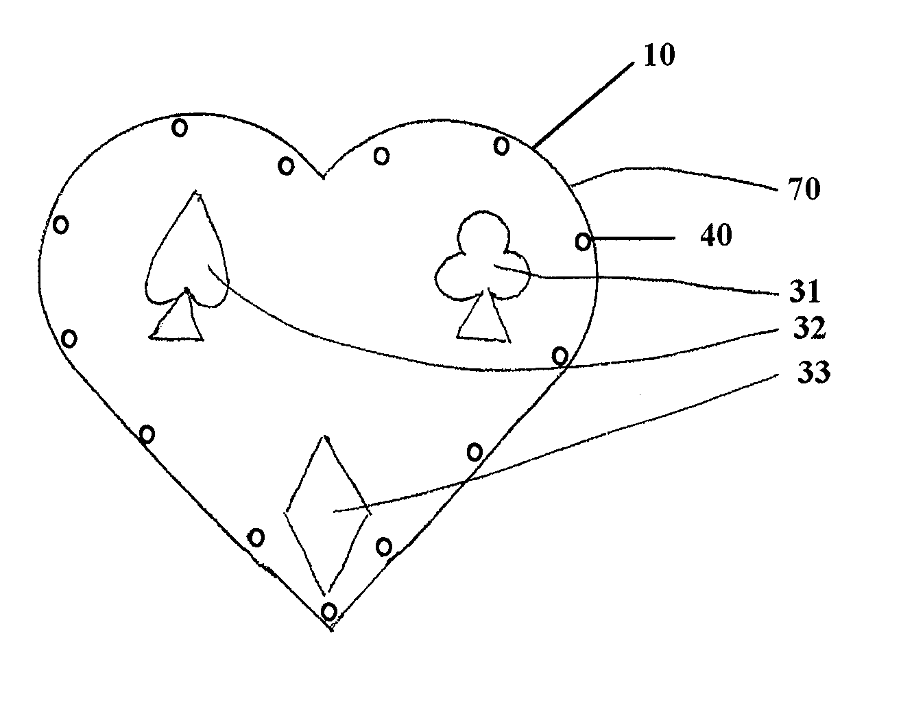
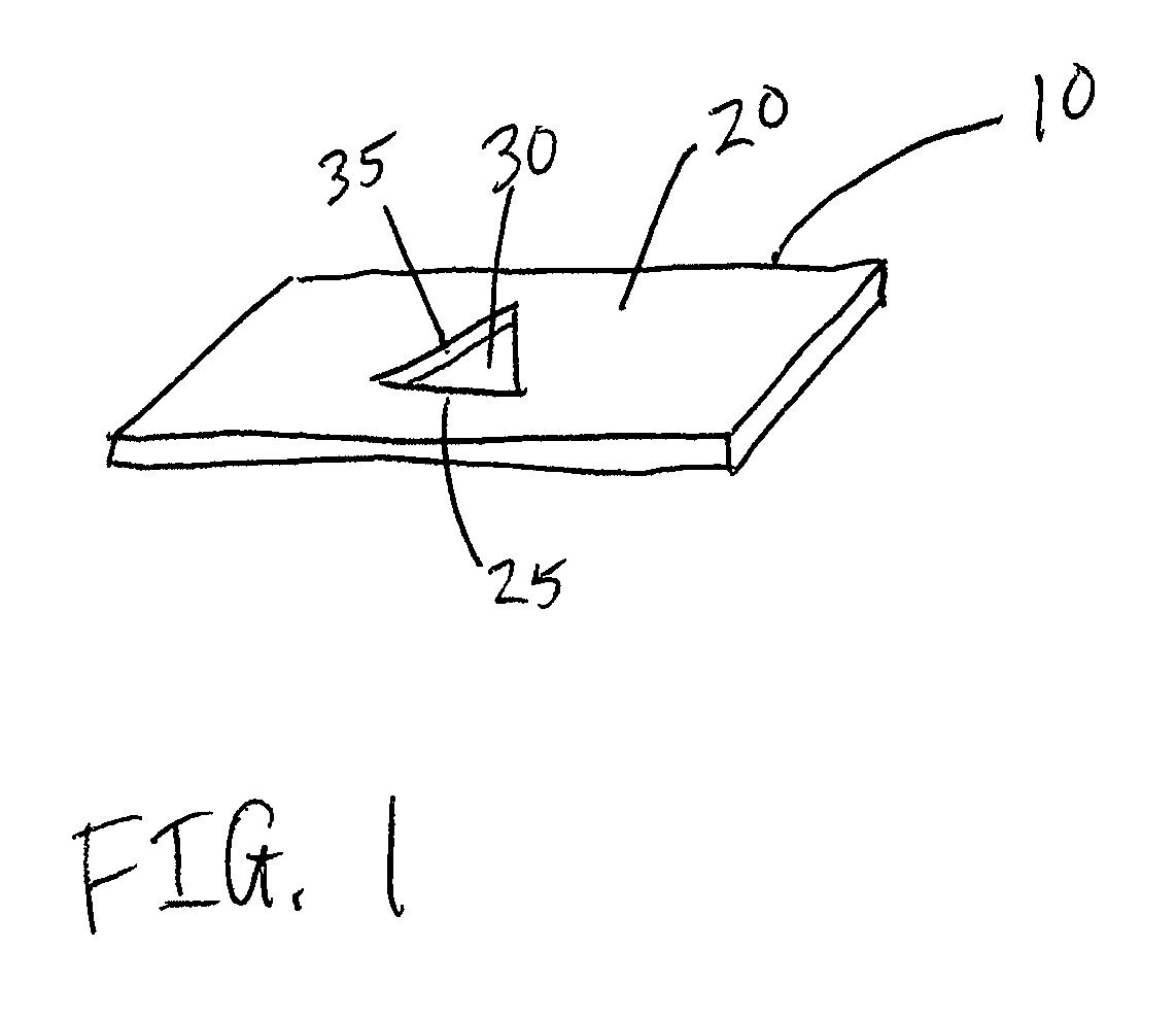
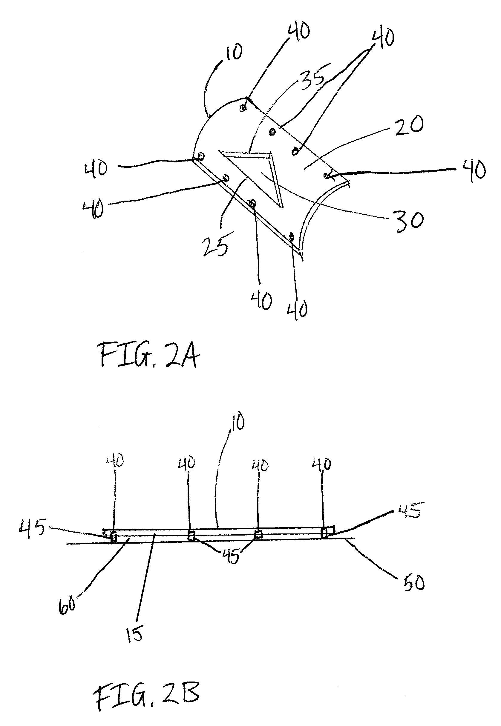
[0005]The embodiments disclosed herein provide a device suitable for assisting cutting and / or marking metal, such as sheet metal, comprising a template member which may be affixed or attached to a surface of the metal. Some embodiments may further comprise a template member and a magnetic component. The template member may further comprise a solid substrate material or a solid component and an outer edge and / or a window component. The device may be configured so that the magnetic component allows the template member to be affixed to a metal object so that the outer edge and / or the boundary of the window component may be used as a guide for cutting the metal, and allows the component to be removed from the metal when it is no longer needed for cutting.
[0006]Some embodiments provide a device suitable for assisting the cutting of metal, such as sheet metal, comprising: a template member comprising a solid substrate material having an outer edge; and a magnetic component, coupled to the template member; wherein the device is configured so that the outer edge may be used as a guide for cutting or marking metal, such as sheet metal, with a plasma cutter. In some embodiments, the device is configured so that the magnetic component provides a magnetic field of sufficient strength to allow the template member to be attached to the metal so that the outer edge may be effectively used as a guide for cutting or marking the metal with a plasma cutter. In some embodiments, the device is further configured so that the magnetic component provides a field which is sufficiently weak to allow the device to be effectively removed from the metal without substantially damaging the template member or the metal.
[0007]Some embodiments provide a device suitable for assisting the cutting of metal, such as sheet metal, comprising: a template member comprising a solid substrate material; a window component of the template member, comprising a pattern characterized by an area devoid of the solid substrate material, and a boundary around the area defined by the solid substrate material of the template member; a magnetic component, coupled to the template member; and at least three spacing members, configured to contact the metal, such as sheet metal, and coupled to the template member; wherein the device is configured so that the boundary of the window component may be used as a guide for cutting or marking metal, such as sheet metal, with a plasma cutter. In some embodiments, the device is configured so that the magnetic component provides a magnetic field of sufficient strength to allow the template member to be attached to the metal so that the boundary of the window component may be effectively used as a guide for cutting the metal, such as sheet metal, with a plasma cutter. In some embodiments, the device is further configured so that the magnetic component provides a field which is sufficiently weak to allow the device to be effectively removed from the metal without substantially damaging the template member or the metal; and wherein the device is configured so that the spacing members have a thickness such that, when all spacing members are disposed between and make contact with both the template member and the sheet metal, the resulting space between the template member and the sheet metal is effective to reduce a loss of force of the attachment between the template member and the metal caused by a mismatch between a contour of the surface of the metal and a contour of a surface of the template.

Problems solved by technology

Conventionally, the incisions made by plasma cutters were controlled by expensive equipment.

Method used


Image

  • Template devices for cutting and marking sheet metal
  • Template devices for cutting and marking sheet metal
  • Template devices for cutting and marking sheet metal

Examples


Embodiment Construction

[0021]Some embodiments provide a device comprising a template member comprising a solid component and an outer edge and / or a window component, and a magnetic component, coupled to the template member. These devices are generally useful for assisting the cutting and marking of metals, such as sheet metal.

[0022]The template member may comprise a solid component and an outer edge and / or a window component. In some embodiments, the solid component may comprise any solid substrate material, such as a metallic material, including aluminum, tin, iron, magnesium, zinc, titanium, copper, etc., or a combination or an oxide thereof; a polymeric material such as a polyalkylene (such as polyethylene, polypropylene, etc.), an acrylate (such as polyacrylic acid, polymethyl methacrylate, polymethyl acrylate, etc.), an epoxy, a fluorocarbon (such as polytetrafluoroethylene, polyvinylidine difluoride, etc.), a functionalized vinyl polymer (such as polyvinyl chloride, also referred to as PVC, polyviny...


PUM

PropertyMeasurementUnit
thicknessaaaaaaaaaa
diameteraaaaaaaaaa
diameteraaaaaaaaaa

Abstract

The embodiments disclosed herein provide a device suitable for assisting cutting and / or marking metal, such as sheet metal, comprising a template member, and optionally, an attachment component such as a magnetic component. The template member may further comprises a solid substrate material or a solid component and an outer edge and / or a window component. The device is configured so that the magnetic component allows the template member to be affixed to a metal object so that the outer edge and / or the window component may be used as a guide for cutting the metal, and allows the component to be removed from the metal when it is no longer needed for cutting.

Description

BACKGROUND OF THE INVENTION[0001]1. Field of the Invention[0002]The embodiments described herein relate to templates which may be useful in cutting sheet metal and objects made from sheet metal.[0003]2. Description of the Related Art[0004]Traditionally, many devices have been used to cut sheet metal, such as various saws or sheering devices. For heating, ventilation, and air conditioning (HVAC) applications, there has been an ongoing need for a quicker and cleaner method of cutting openings in warm air pipes, which are made from sheet metal, to install retrofit dampers. Recently, plasma cutters have become more affordable, and are being used more frequently by individuals for cutting sheet metal. Conventionally, the incisions made by plasma cutters were controlled by expensive equipment. However, as plasma cutters have become more commonplace and affordable, there is a need for an inexpensive template device to assist in cutting sheet metal in applications such as HVAC.SUMMARY OF TH...

Claims


Application Information

Patent Timeline
Patent Type & Authority Patents(United States)
IPC IPC(8): B23K9/00
CPCB23K10/00B23K9/32Y10T83/8878Y10T83/04
Inventor GOODMAN, JR., DONALD L.
Owner GOODMAN JR DONALD L
Learn More