Electromagnetic Spectrum Management System

Active Publication Date: 2016-10-06
NAT SECURITY TECH
View PDF0 Cites 0 Cited by
  • Summary
  • Abstract
  • Description
  • Claims
  • Application Information

AI Technical Summary

Benefits of technology

The invention combines two methods of interference, SIGINT and ECM, to create a new way of controlling the electromagnetic spectrum. This technology makes it possible to disrupt the modulation of all other bands while still allowing data and voice communications on "friendly" bands. It also reduces the power needed for RF jamming protection and offers variable output gain to adjust the circumference of protection.

Problems solved by technology

As a specific example, military operators and domestic first responders are constantly threatened by improvised explosive devices (IEDs), vehicle-borne improvised explosive devices (VBIEDs), radiological dispersion devices (RDDs), and other penalties.
Also, responders and operators do not always have prior knowledge of the threat spectrum and have had to presume against what specific threats to protect.
The current prior art is limited to either receiving radio frequency (RF) signals for signal intelligence (SIGINT) or transmitting RF signals as electronic countermeasures (ECM).
Both of these prior art options suffer from disadvantages.
The high power, all channel jammer approach utilizes too much power because all channels are flooded with high power jammer signals.
This approach also prevents friendly communications because all channels are flooded with high power jamming signals.
The selective jammer approach sends out a jamming signal on certain channels, but difficulties arise in determining which channels to jam and which to leave open.
Channels left unjammed created an unwanted risk for first responders or other personnel.
Additionally, this art greatly reduces the power needed to provide RF jamming protection and offers variable output gain to adjust the circumference of protection.
This can provide incorrect data or information to an enemy.

Method used


Image

  • Electromagnetic Spectrum Management System
  • Electromagnetic Spectrum Management System
  • Electromagnetic Spectrum Management System

Examples


Embodiment Construction

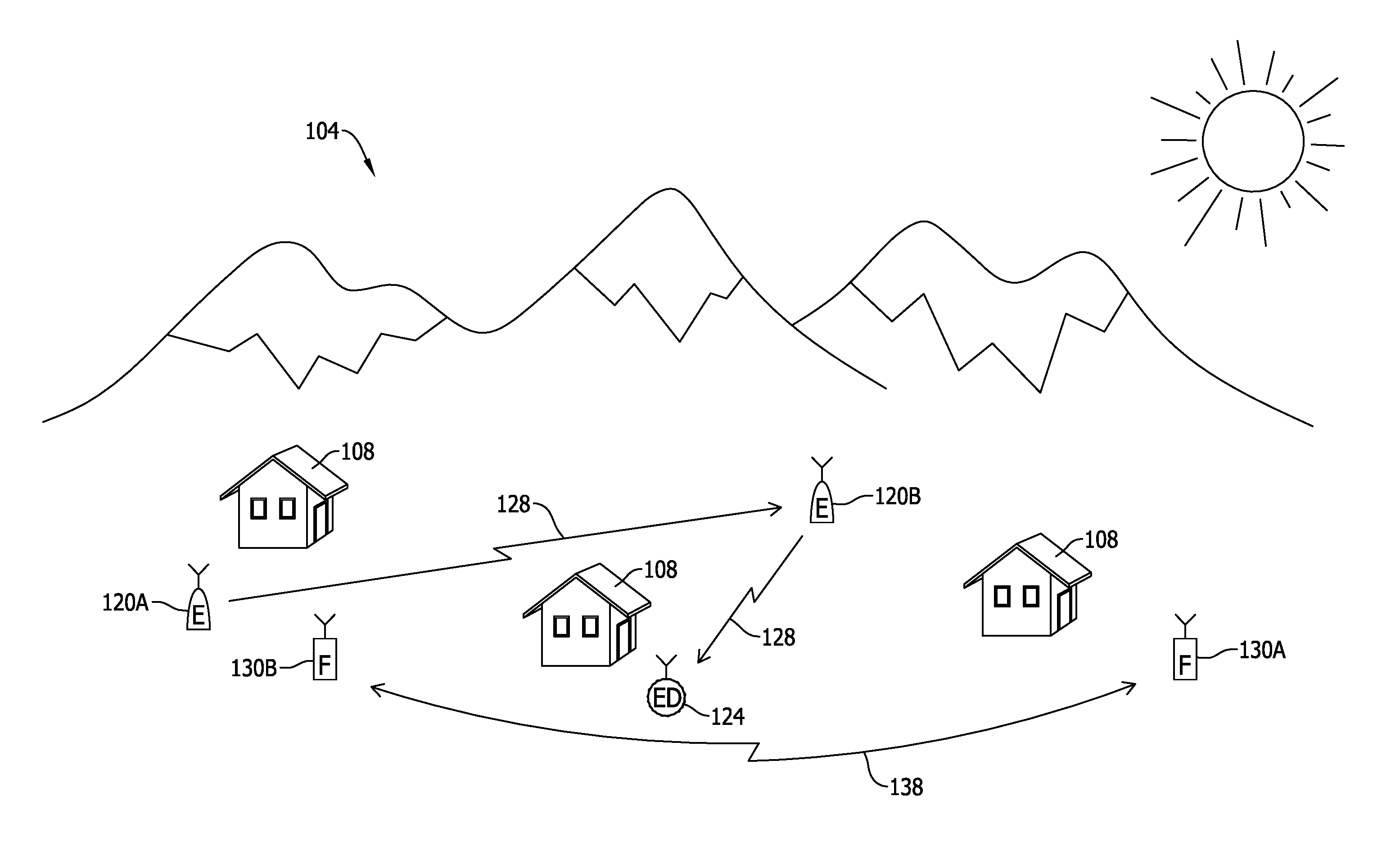
[0031]FIG. 1 is an example environment of use of the present invention. This is but one possible exemplary environment of use. It is contemplated that the present invention may find use in any environment where it is desired to limit or prevent communication between third parties, while optionally allowing communication between known parties or known communication devices. The environments of use may be in urban or rural areas, inside or outside, at any elevation, in air, sea, or land environments or in space.

[0032]In FIG. 1, an example environment of use 104 is shown that includes both rural and urban components. One or more buildings 108 are shown. Friendly communication devices 130A, 130B are capable of communication over a wireless communication channel 138 to exchange voice, data, or both. It is desired to maintain communication between friendly devices, operated by known and / or friendly personnel as is understood in the art to allow for coordination and tactical effectiveness....


PUM


Abstract

A system for transmitting a wireless countermeasure signal to disrupt third party communications is disclosed that include an antenna configured to receive wireless signals and transmit wireless counter measure signals such that the wireless countermeasure signals are responsive to the received wireless signals. A receiver processes the received wireless signals to create processed received signal data while a spectrum control module subtracts known source signal data from the processed received signal data to generate unknown source signal data. The unknown source signal data is based on unknown wireless signals, such as enemy signals. A transmitter is configured to process the unknown source signal data to create countermeasure signals and transmit a wireless countermeasure signal over the first antenna or a second antenna to thereby interfere with the unknown wireless signals.

Description

2. PRIORITY CLAIM[0001]This application claims priority to and the benefit of U.S. provisional patent application 62 / 142,979 entitled Electromagnetic Spectrum Management System filed on Apr. 3, 2015.1. STATEMENT REGARDING FEDERAL RIGHTS[0002]This invention was made with government support under Contract No. DE-AC52-06NA25946 and was awarded by the U.S. Department of Energy, National Nuclear Security Administration. The government has certain rights in the invention.3. FIELD OF THE INVENTION[0003]This innovation relates to spectrum management for wireless communications systems and in particular to a method and apparatus for concurrent transmit and receive functions as part of electronic countermeasures.4. RELATED ART[0004]When transmitting information over a wireless channel, the wireless signal is transmitted by a transmitter into free space to be received by a receiver at a remote location. As with many broadcast formats, the wireless signal may be freely received by any party wit...

Claims


Application Information

Patent Timeline
IPC IPC(8): H04K3/00
CPCH04K3/43H04B1/0007H04B14/04H04K3/28H04K3/41H04K3/42H04K3/44H04K3/45H04K3/825H04K2203/34H04B1/04H04B1/69H04B2001/0416H04B2201/70727
Inventor SEASTRAND, DOUGLAS R.
Owner NAT SECURITY TECH
Why Eureka
Try Eureka