
Charging device for mobile phone

Inactive Publication Date: 2005-12-08
LIN CHENG KUANG
View PDF4 Cites 46 Cited by
  • Summary
  • Abstract
  • Description
  • Claims
  • Application Information

AI Technical Summary

Benefits of technology

[0010] Another object of the present invention is to provide a charging device for mobile phone that includes a pair of pins, which can be rotated and selectively coupled with differently structured plugs, enabling the charging device to be flexibly used in different areas or countries.
[0011] A further object of the present invention is to provide a charging device for mobile phone that is provided with contacts for engaging with a 9V battery, so that the charging device can also be battery-powered and is more practical for use.

Problems solved by technology

While the conventional mobile phone battery chargers are easy to use and convenient to carry, they have some drawbacks.
For example, the long power cord connected to the housing of the charger prevents the charger from easy storage and convenient carrying.
The long power cord extended between a power supply and a mobile phone is subject to unexpected pull that might result in undesired separation of the plug of the charger from the power receptacle, and accordingly, interruption of power supply to the charger.
In a worse condition, the mobile phone connected to the second end of the long power cord is damaged due to dropping to floor when the power cord is forcedly pulled.
Another problem with the use of the conventional mobile phone battery charger is the charger usually has a fixed plug structure while the power receptacles often vary from country to country, preventing the charger with a fixed plug from being used in different areas or countries and bringing confusions and inconveniences to a user traveling overseas.
Moreover, the conventional mobile phone battery chargers are normally powered with alternating current and could not be used outdoors, in a power failure, or at places without an AC power receptacle.

Method used


Image

  • Charging device for mobile phone
  • Charging device for mobile phone
  • Charging device for mobile phone

Examples


Embodiment Construction

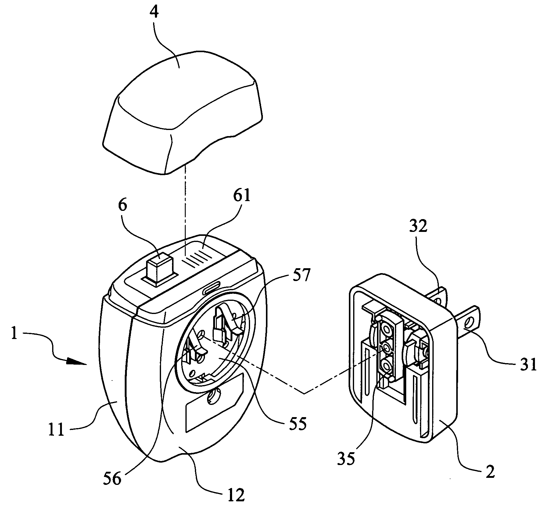
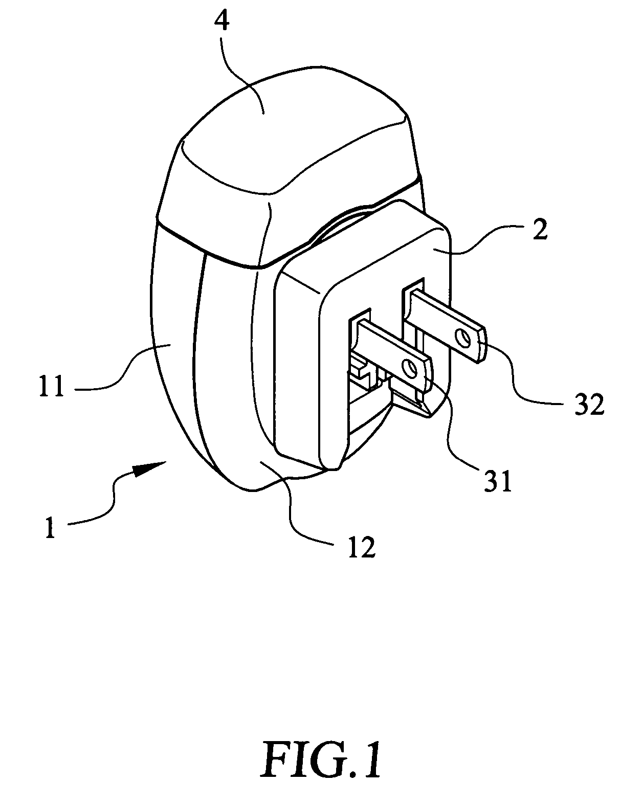
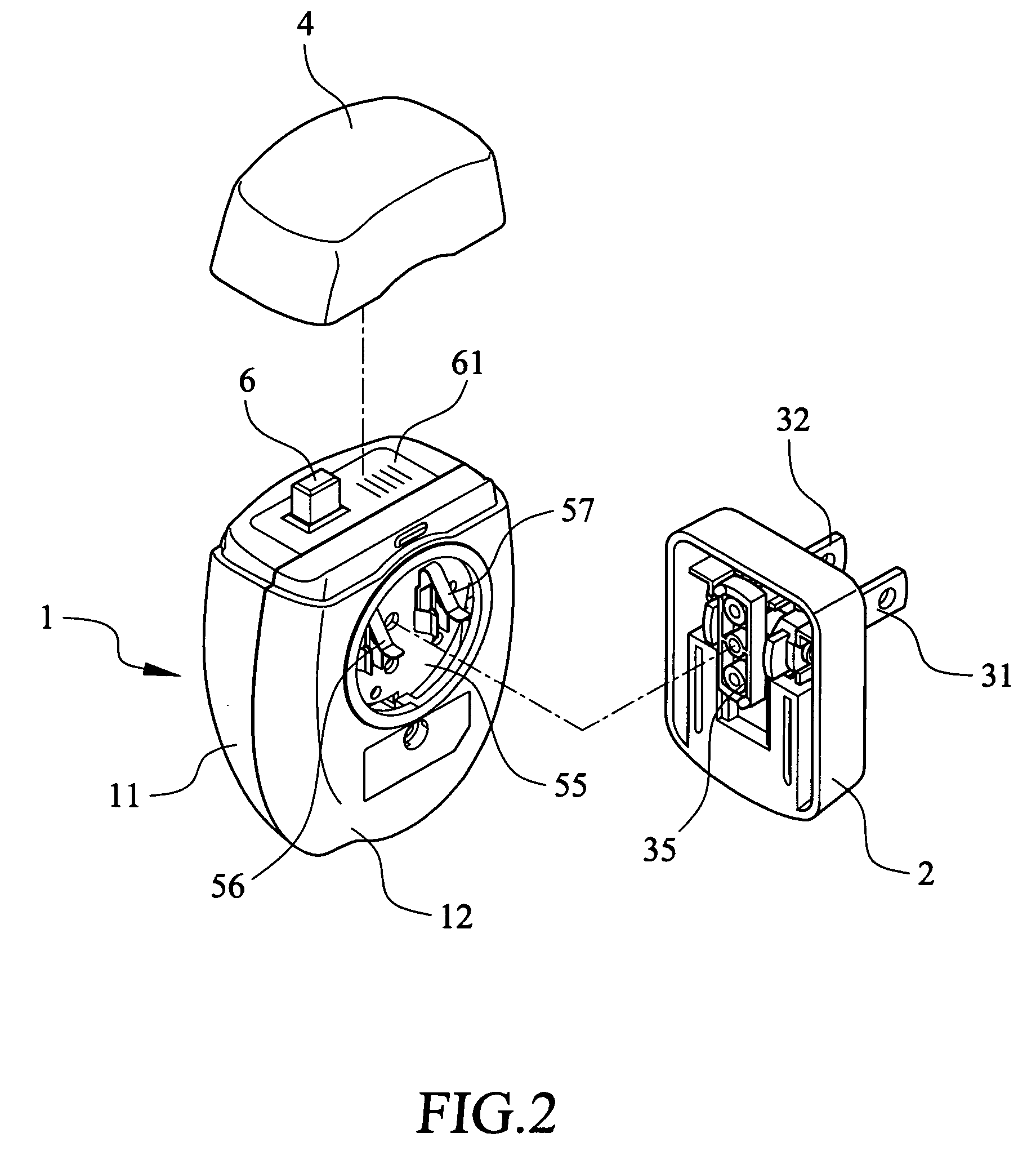
[0025] Please refer to FIGS. 1 and 2 that are fully assembled and partially exploded perspective views, respectively, of a charging device for mobile phone according to the present invention. As shown, the charging device for mobile phone mainly includes a main body 1, a pin-rotating member 2, a pair of pins 31, 32, and a protective cap 4 removably covering a top of the main body 1. The protective cap 4 protects the charging device against dust and oxidization of exposed metal parts when the charging device is not in use, and thereby prolongs a usable life of the charging device. The protective cap 4 also gives the whole main body 1 a beautifully streamlined appearance and makes the charging device more convenient for carrying and storage.

[0026] Please refer to FIG. 3 that is a fully exploded perspective view of the present invention. As shown, the main body 1 includes a first and a second housing 11, 12 that are connected together to define an internal space therebetween for recei...


PUM


Abstract

A charging device for mobile phone includes a main body; a rotatable pin-rotating member having two pins connected thereto for leading in alternating current; a contact conduction mechanism located between the pin-rotating member and a circuit board in the main body to conduct alternating current from the pins to the circuit board; a mobile phone rest base for a mobile phone to engage therewith and be charged; and battery contacts for a 9V battery to connect thereto. The contact conduction mechanism includes an annular seat having multiple contacts provided thereon, a pair of conducting strips, a turnable disc, and a pair of pin contactors sequentially fixed to a front side of the circuit board to align and associate with the pin-rotating member, so that AC power is led in via the pins to the circuit board even when the pin-rotating member is turned.

Description

BACKGROUND OF THE INVENTION [0001] 1. Field of the Invention [0002] The present invention relates to a charging device for mobile phone, and more particularly to an integrated charging device for mobile phone to include a pair of pins that are freely rotatable and adapted to plug to differently structured power receptacles adopted in different countries, and battery contacts for a 9V battery to connect thereto to charge a mobile phone when an AC power is not available. [0003] 2. Description of the Prior Art [0004] Various types of portable apparatus, such as mobile phones, personal digital assistants, etc., have become indispensable to people living in the modern commercial society. These portable apparatus are powered with one or more batteries to work normally. However, the batteries must be timely recharged to maintain their function of power supply. [0005] In a currently widely used mobile phone battery charger, there are mainly included a housing, a charging seat, a plurality o...

Claims


Application Information

Patent Timeline
IPC IPC(8): H01R31/06H01R35/04H02J7/00
CPCH01R31/065H02J7/0042H01R35/04
Inventor LIN, CHENG-KUANG
Owner LIN CHENG KUANG
Learn More