Direction and distance finder for locating distress signals

a technology of direction finder and distress signal, which is applied in direction finder using radio waves, instruments, reradiation, etc., and can solve problems such as dramatic increase in the slope of the path

Inactive Publication Date: 2005-12-08
ACR ELECTRONICS INC
View PDF5 Cites 39 Cited by
  • Summary
  • Abstract
  • Description
  • Claims
  • Application Information

AI Technical Summary

Benefits of technology

[0010] The present invention provides a system and method for locating the source of a RF signal. The present invention enables a user to locate the source of a RF signal as emitted by a distress beacon during a search and rescue operation. The present invention advantageously not only provides directional data as to the direction of the RF signal source, but also provides an estimated distance between a receiver and the RF signal source. A receiver according to the present invention advantageously provides direction and distance estimates based upon signal strength in a certain direction or over a certain distance.
[0011] In one exemplary embodiment of the present invention, a searcher using a signal locator (RF receiver) obtains the direction of the RF signal source, i.e., the distress beacon. The direction may be ascertained based upon signal strength readings taken by the locator where the strongest signal reading emits from the direction of the beacon. After obtaining the signal direction, the locator stores the initial RF signal strength reading and provides an estimated distance reading. The initial directional data and distance data provide an initial way point reading. The user may then proceed in the indicated direction and the locator produces continuous subsequent way point readings. The subsequent distance readings may be determined based upon the path loss slope of the received RF signals. As the distance between the receiver and beacon decreases, the path loss slope dramatically increases. The path loss slope is the x-y graph of the beacon signal power strength as a function of distance from the receiver to the RF beacon. The present invention advantageously exploits this phenomenon in order to provide accurate and effective distance estimations.
[0015] The present invention also provides a system and method for locating an avalanche victim. Many of the avalanche rescue systems that are currently being manufactured use an avalanche beacon that transmits an RF signal at 457 kHz (amplitude modulated) that is attached to the person buried in the avalanche for location. Typically, the victim's transmitter emits a dipole flux pattern (magnetic field pattern). The present invention enables a searcher with a receiver built in accordance with the present invention to locate the source of this transmitted field as emitted by a distress beacon during a search and rescue operation. The present invention not only provides point to point directional data as to the direction of the RF field source based on flux field characteristics, but also provides an estimated distance between the searcher's receiver and the victim's transmitter field source using path loss slope and / or triangulation. A receiver in accordance with the present invention advantageously provides direction and distance estimates based upon field signal strength transmitted by the victim's transmitter avalanche or field strength changes in a certain direction with regard to the flux lines and / or over a certain distance.

Problems solved by technology

As the distance between the receiver and beacon decreases, the path loss slope dramatically increases.

Method used


Image

  • Direction and distance finder for locating distress signals
  • Direction and distance finder for locating distress signals
  • Direction and distance finder for locating distress signals

Examples


Embodiment Construction

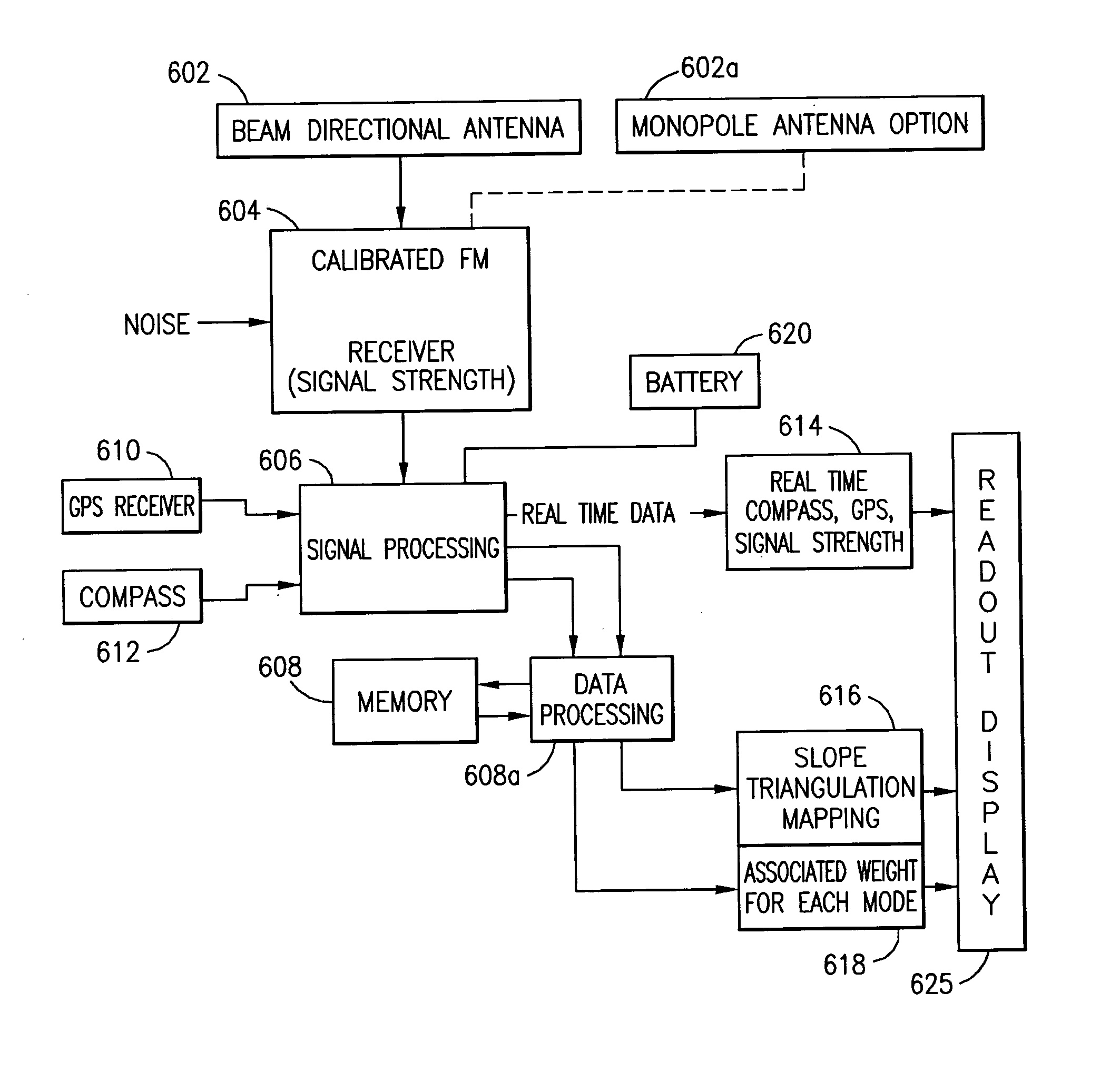
[0029] The present invention provides a system and method that enables swift and accurate location of a RF signal source such as emitted by a distress beacon. The present invention advantageously uses path loss slope readings in order to eventually locate the RF signal source that is transmitted by the distress beacon. The present invention enables a user to acquire data with a handheld device and determine direction and distance of a RF signal source. The direction is determined based upon signal strength and the distance reading may be determined based upon power level changes that occur over the distance traveled, defined as power path loss slope.

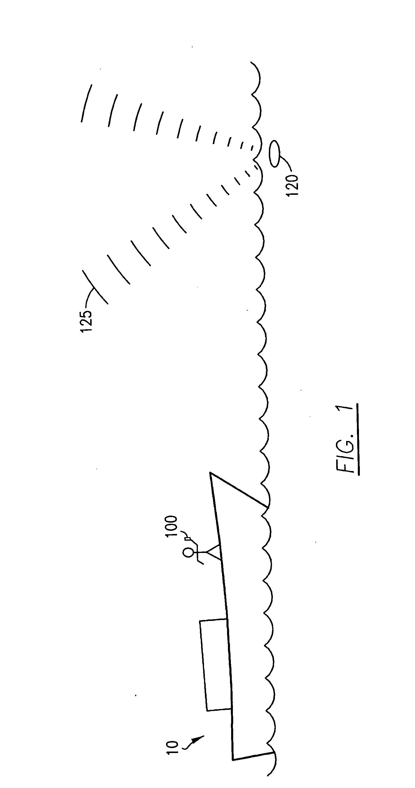
[0030] Referring now to FIG. 1, a symbolic exemplary overview of a rescue directional locating system according to the present invention is shown. A RF transmitting beacon 120 floats on a body of water or is attached or held above the water by a person requiring location and rescue depicting a search and rescue situation. However, the p...


PUM


Abstract

The present invention relates to a system and method for locating the direction and distance to a RF signal source from an avalanche beacon to find an avalanche victim. The system and method includes a RF signal locator and a graphical display residing on the signal locator. The receiver graphical display provides the searcher with an initial way point reading that includes directional and distance data associated with the beacon RF signal source from the avalanche beacon. The directional and distance data is based upon the received RF signals. A processor within the locator receiver receives and measures RF signals emitted by the RF signal source. The locator advantageously provides continuous subsequent way point readings for the user, where the subsequent way point readings include directional and distance data associated with the RF signal source. The distance data provided by the subsequent way point readings is based upon a path loss slope of the received RF signals from the avalanche beacon.

Description

[0001] This is a continuation-in-part of U.S. application Ser. No. 10 / 709,656 filed May 20, 2004 and of Provisional U.S. Application Ser. No. 60 / 477,125 filed Jun. 9, 2003.BACKGROUND OF THE INVENTION [0002] 1. Field of the Invention [0003] The present invention relates to a direction and distance estimation system and method based upon characteristics of the Radio Frequency (RF) and the power path loss curve to locate victims. [0004] 2. Description of Related Art [0005] Aircraft emergency locator systems such as ELTs (Emergency Locator Transmitters) and terrestrial location systems such as PLBs (Personal Locator Beacons) are well known in the existing art. Individuals lost at sea and fortunate enough to have emergency location identification devices such as an Emergency Position Indicating Radio Beacon (EPIRB), can send out RF signals with the hopes that their distress signals will be picked up by maritime stations or satellites, which can in turn, relay the information to the prope...

Claims


Application Information

Patent Timeline
Patent Type & Authority Applications(United States)
IPC IPC(8): A63B29/02G01S3/40G01S11/06G01S13/00G01S19/48
CPCA63B29/021G01S11/06G01S3/40
Inventor WOLF, EDWARD A.CLARK, MARK
Owner ACR ELECTRONICS INC
Why Eureka
Try Eureka