
Golf flagstick assembly and method of joining

a golf and flagstick technology, applied in the field of golf course accessories, can solve the problems of difficult placement of adhesives, difficult to place adhesives, and investment in development and equipment, and achieve the effect of eliminating nuisance fiberglass dust and removing the connection

Inactive Publication Date: 2005-12-08
STANDARD GOLF
View PDF9 Cites 44 Cited by
  • Summary
  • Abstract
  • Description
  • Claims
  • Application Information

AI Technical Summary

Benefits of technology

[0011] According to another features of the present invention, the method of joining provides a secure attachment that provides an accurate method of centering an accessory onto a flagstick rod.
[0012] According to another feature of the present invention, the method eliminates nuisance fiberglass dust during the attachment process which may create a problem on some joining applications.
[0013] According to another feature of the present invention, the method provides for the removal of the connection between the flagstick rod and the accessory with relative ease and to optionally place upon another flagstick rod.

Problems solved by technology

Adhesive creates a number of problems and difficulties.
Adhesive is difficult to place within the interface between the rod and the accessory, requires a curing time for the adhesive to set, and the prior art flagsticks provide no structure for positively aligning the golf flagstick with the accessory.
The prior art golf flagstick assemblies did not require accurate alignment of golf stick accessories and flagsticks.
Instead, the prior art was largely concerned with securing the accessory to the flagstick costs and therefore did not invest into the development and equipment for precise alignment of golf flagsticks.
Moreover, the requirement for precisely aligned golf flagstick assemblies was not evident until precision distance measuring tools were available that utilized accessories for laser sighting placed upon the golf flagstick.
With several joints, the cumulative affects of using adhesive at these joints may create a misaligned golf flagstick assembly.

Method used


Image

  • Golf flagstick assembly and method of joining
  • Golf flagstick assembly and method of joining
  • Golf flagstick assembly and method of joining

Examples


Embodiment Construction

[0027] The present invention will be described as it applies to its preferred embodiment. It is not intended that the present invention be limited to the described embodiment. It is intended that the invention covers all alternatives, modifications, and equivalents which may be included within the spirit and scope of the invention.

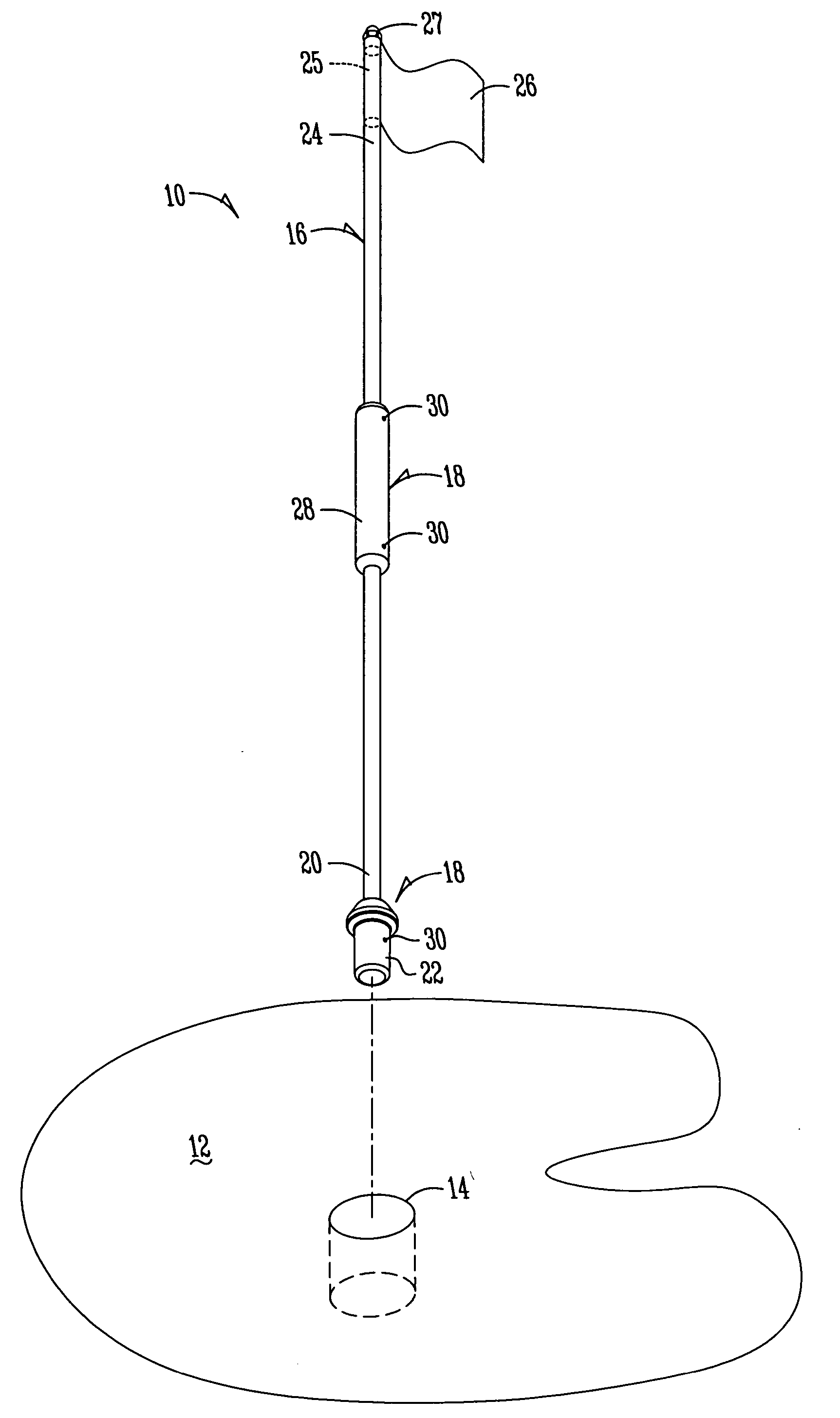
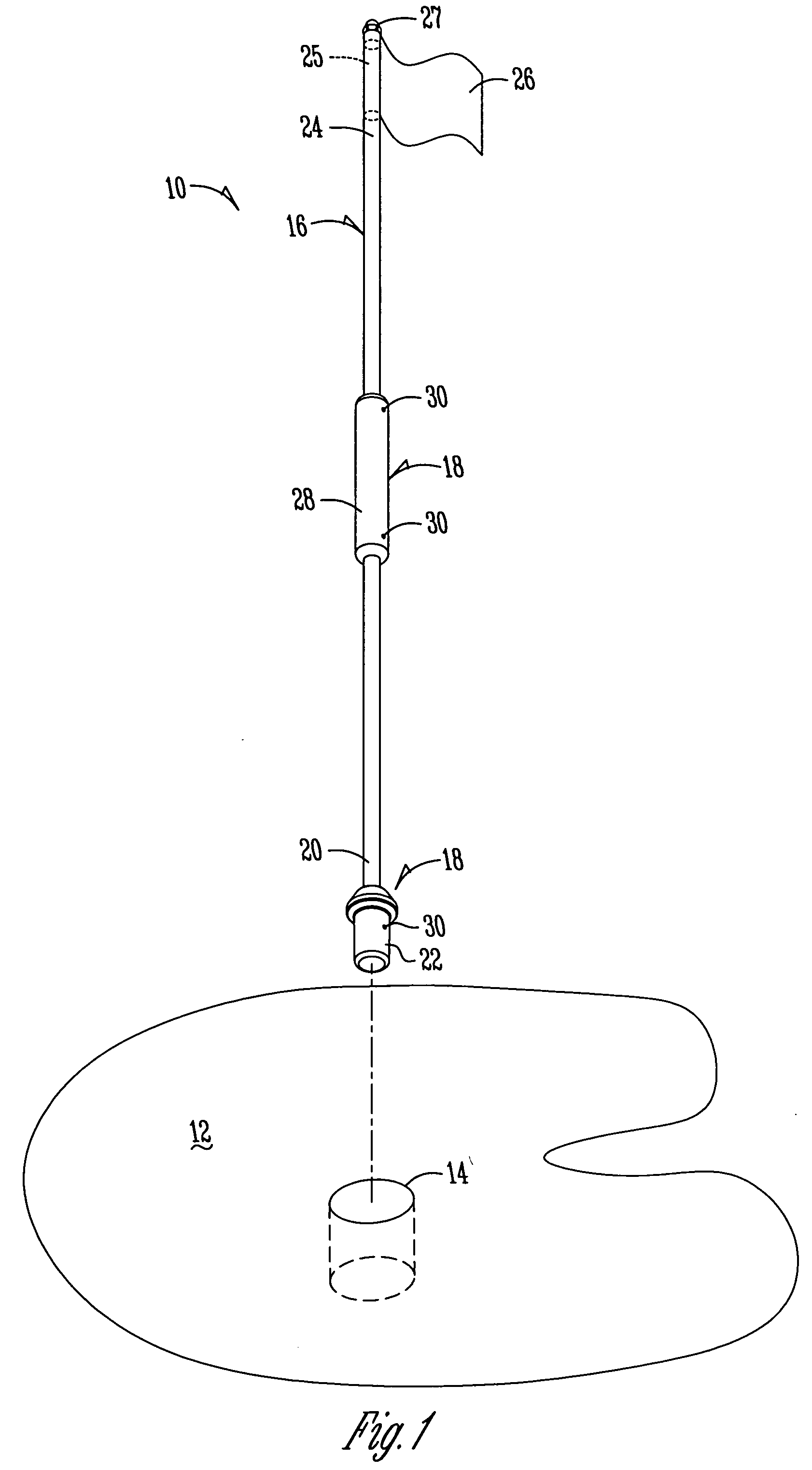
[0028]FIG. 1 shows the golf flagstick assembly 10 of the present invention. The golf flagstick assembly 10 is shown in use on a putting green 12 that has a golf putting cup 14 located upon it.

[0029] The golf flagstick assembly 10 has a golf flagstick 16 with attachment piece or accessory 18 located upon it.

[0030] The golf flagstick has a first end 20 having an attachment piece 18 that is a ferrule 22. The ferrule22 is designed to mate with the golf putting cup 14 to maintain the golf flagstick assembly 10 perpendicular with a plane defined by the top of the opening of the putting cup 14.

[0031] The golf flagstick 16 has a second end 24 upon which a flag...


PUM


Abstract

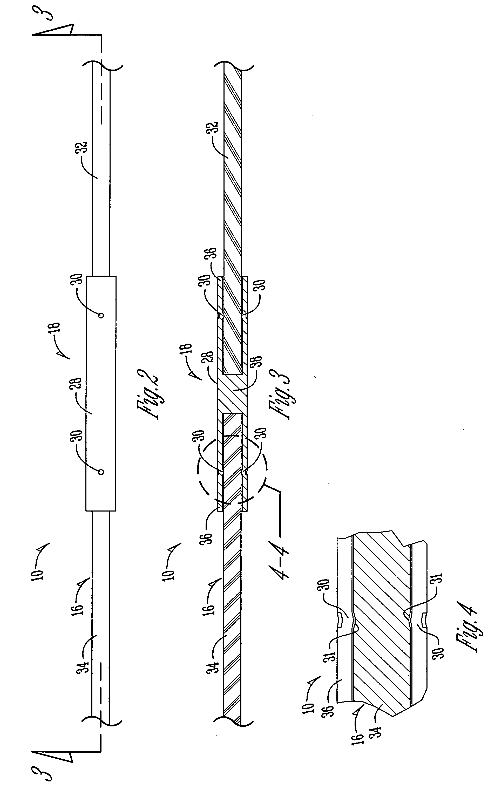
A golf flagstick assembly includes a flagstick and an accessory aligned substantially straight with each other along a common longitudinal centerline. The flagstick and the accessory are rapidly joined together utilizing crimps upon the accessory which engage the flagstick. The accessory may be joined to the golf flagstick assembly at either end or between the ends. The method includes the steps forming an assembly by placing the rod within the accessory and joining in alignment the assembly by crimping the accessory at balanced locations around a circumference of the accessory to press against the flagstick.

Description

BACKGROUND OF THE INVENTION [0001] The present invention relates generally to the field of golf course accessories and, more particularly, to a golf flagstick assembly and method of joining the same. [0002] In prior art golf flagsticks, adhesive is used for joining a golf flagstick to an accessory placed upon the golf flagstick. Adhesive creates a number of problems and difficulties. Adhesive is difficult to place within the interface between the rod and the accessory, requires a curing time for the adhesive to set, and the prior art flagsticks provide no structure for positively aligning the golf flagstick with the accessory. [0003] The prior art golf flagstick assemblies did not require accurate alignment of golf stick accessories and flagsticks. Instead, the prior art was largely concerned with securing the accessory to the flagstick costs and therefore did not invest into the development and equipment for precise alignment of golf flagsticks. Moreover, the requirement for precis...

Claims


Application Information

Patent Timeline
IPC IPC(8): A63B57/00A63B69/36G09F17/00
CPCG09F17/00A63B57/357A63B57/40
Inventor HURLEY, MATTHEW L.SAUL, RON L.HOTTLE, SCOTT M.
Owner STANDARD GOLF
Learn More