Contact lenses and methods for their design

a technology of contact lenses and lenses, applied in the field of contact lenses, can solve problems such as suboptimal lens performan

Active Publication Date: 2005-12-15
JOHNSON & JOHNSON VISION CARE INC
View PDF3 Cites 8 Cited by
  • Summary
  • Abstract
  • Description
  • Claims
  • Application Information

AI Technical Summary

Benefits of technology

[0008] Additionally, the monofocal lenses of the invention provide performance that minimizes the wearer's normally required optical cylinder without the need to include toricity in the lens due to the sharper image provided by the lens, which compensates for some of the blurring of image due to the wearer's cylinder. As yet another advantage, the lenses of the invention can be used to provide accommodation for near and intermediate distance tasks for emerging presbyopes. More specifically, the lenses of the invention may be useful for correcting near vision acuity of individuals who need less than about 1.75 diopters, preferably less than or equal to about 1.5 diopters of add power.
[0009] In one embodiment, the invention provides a soft contact lens comprising, consisting essentially of, and consisting of a back surface having a shape suitable to substantially inversely match a corneal shape and an aspheric front surface, wherein the lens' optical performance for one or more of pupil size, field, and lens centration is optimized. In another embodiment, the invention provides a method of designing a soft contact lens comprising, consisting essentially of and consisting of the steps of shaping a back surface of a lens to substantially inversely match a corneal shape, providing an aspheric front surface and optimizing the optical performance of the front surface of the lens for one or more of pupil size, field, and lens centration.

Problems solved by technology

This method of lens design fails to take into account the effects of field and decentration when the contact lens wraps on the cornea resulting in suboptimal lens performance.

Method used


Image

  • Contact lenses and methods for their design
  • Contact lenses and methods for their design
  • Contact lenses and methods for their design

Examples


example

[0041] The performance of a lens designed according to the method of the invention and a lens designed using a paraxial optical design method in air were compared. The paraxial design, Lens A, was an ACUVUE® 2 BRAND etafilcon lens of −3.00 diopters. The Lens A design was wrapped onto a nominal cornea using Finite, Element Analysis (“FEA”) techniques. The lens shape resulting from the FEA was then loaded into the ZEMAX optical ray trace program.

[0042]FIGS. 3 and 4 are charts below comparing the 0 and 5 degree field RMS spot size at up to ±−0.5 diopters from the central design point of the wrapped Lens A design to a lens design of the invention, Lens B. Lens B is a −3.00 diopters etafilcon lens. The merit function used for Lens B was the RMS spot size at focus, with a ±5 degree field and a 0.5 mm decentration in ±X and ±Y directions. At these decentered conditions, the fields were optimized for RMS spot size at a 0 degree field and at ±5 degrees fields in X and Y. The total number of...


PUM


Abstract

The invention provides lenses that are designed by taking into account one or more of pupil size, field, and decentration.

Description

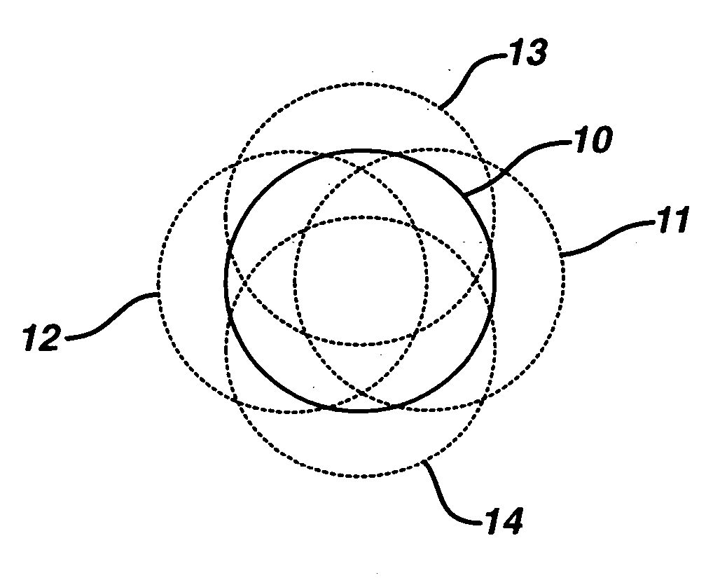
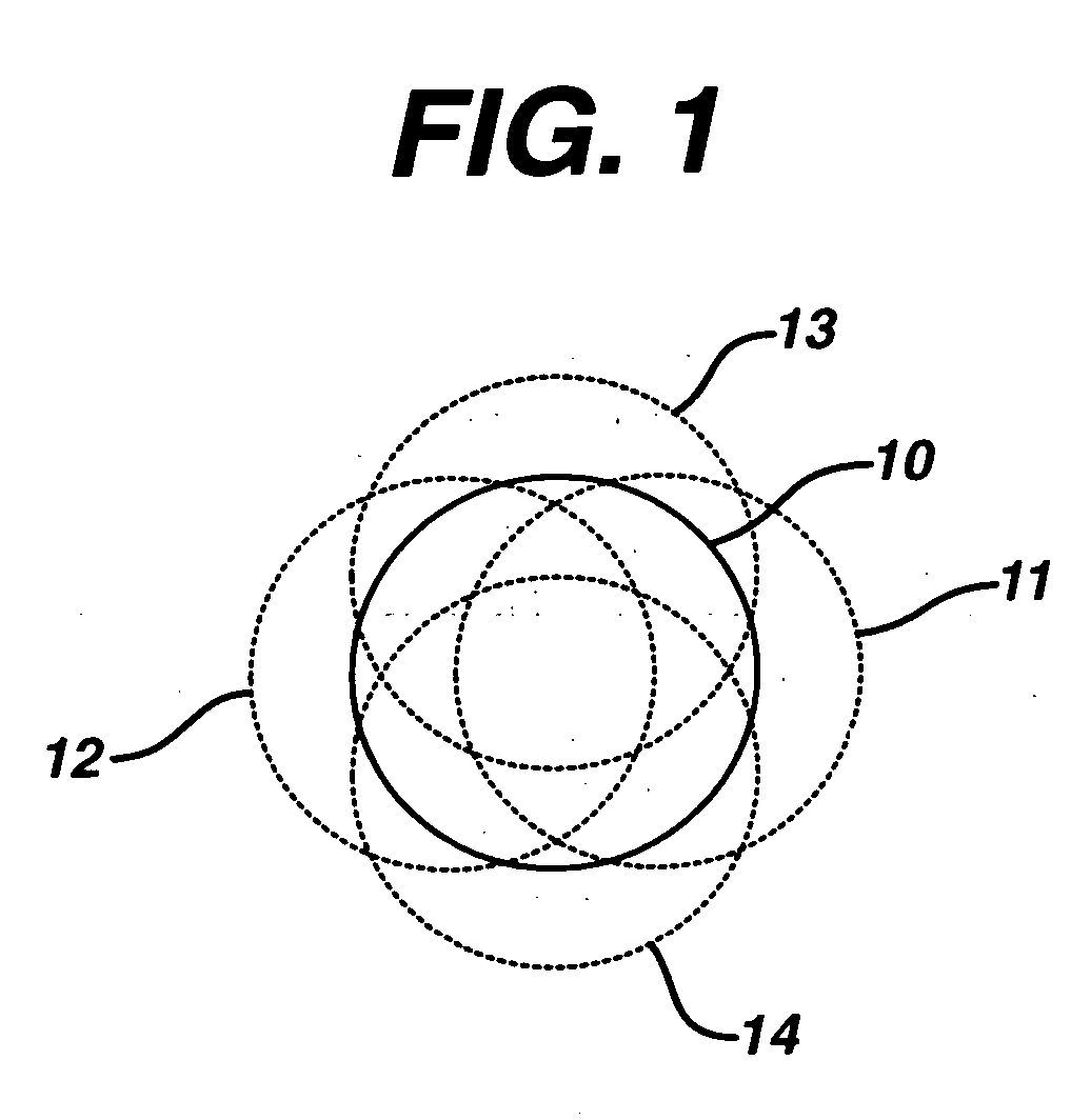
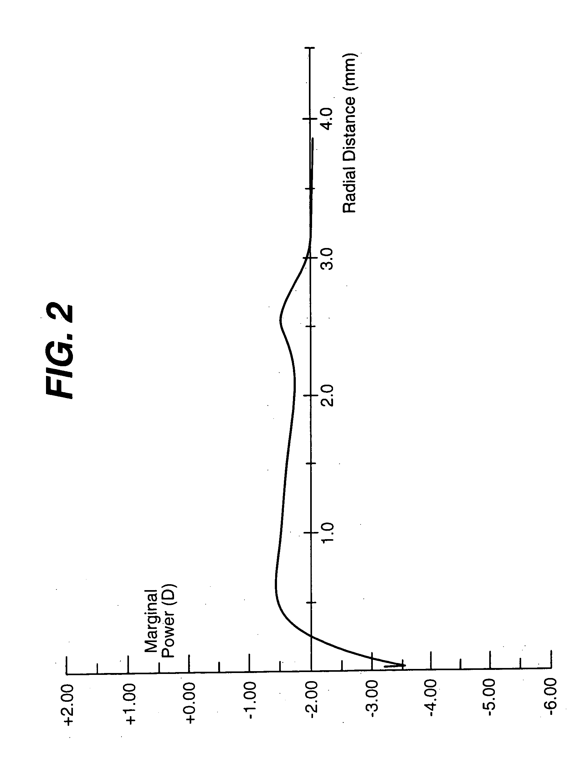
FIELD OF THE INVENTION [0001] The invention relates to contact lenses. In particular, the invention provides contact lenses designed by taking into account the effects of field and decentration when the lens is on-eye. BACKGROUND OF THE INVENTION [0002] The use of soft contact lenses for correction of visual acuity defects is widely accepted. Typically, soft contact lenses are designed in air using simple, paraxial modeling. This method of lens design fails to take into account the effects of field and decentration when the contact lens wraps on the cornea resulting in suboptimal lens performance. Therefore, a need exists for contact lenses and method of lens design that improve lens performanceBRIEF DESCRIPTION OF THE DRAWINGS [0003]FIG. 1 is a depiction of decentration locations used in one embodiment of the design method of the invention. [0004]FIG. 2 is a power curve for a lens of the invention. [0005]FIG. 3 is a chart of the on-axis spot comparison of the lenses of the example....

Claims


Application Information

Patent Timeline
Patent Type & Authority Applications(United States)
IPC IPC(8): G02C7/04
CPCG02C7/028G02C2202/06G02C2202/04G02C7/04
Inventor JONES, LARRY G.HAYWOOD, JAMES W.
Owner JOHNSON & JOHNSON VISION CARE INC
Why Eureka
Try Eureka