Wearing-orientation selectable contact lens

a contact lens and orientation technology, applied in the field of contact lenses, can solve the problems of inability to afford effective correction neither for distance vision nor for near, increase in production cost or management cost, and poor optical characteristics, and achieve excellent manufacturing efficiency

Active Publication Date: 2011-07-12
MENICON CO LTD
View PDF9 Cites 6 Cited by
  • Summary
  • Abstract
  • Description
  • Claims
  • Application Information

AI Technical Summary

Benefits of technology

[0012]It is therefore one object of the present invention to provide a contact lens of novel construction affording vision correction by each diopter power region more effectively.

Problems solved by technology

As a result, it is not possible to afford an effective correction neither for distance vision nor for near vision.
Thus, if the lenses are supplied through made-to-stock production, a lot of stocks need to be prepared, posing a risk of increase in production cost or management cost.
A general problem with the multifocal contact lenses disclosed in EP-A2-0201231 or JP-A-6-289329 is that since the multifocal contact lens includes one optical region with a plurality of diopter power regions, each diopter power region has a narrow effective optical region.
Consequently, optical characteristics are not as good as those of monofocal lenses.
In particular, during the night, their distance vision suffers from flare that occurs due to defocus of the near region, causing poor visibility.
Another risk associated with the multifocal contact lenses is that correction may vary depending on changes in environment such as changes of brightness from day to night, or changes in usage such as changes from operating PC indoors to watching sports outdoors.
Consequently, the multifocal contact lenses optimized under the environment at the time of prescription pose a risk that the wearers become less satisfied with their vision which changes under the different environment or usage conditions.
Furthermore, since multifocal contact lenses have a plurality of diopter powers to be adjusted, the prescription needs more time and labor than in case of monofocal lenses.
Similarly, for the wearers, it takes time to get used to the multifocal contact lenses because of the unique vision thereof different from that of monofocal lenses.
However, monovision prescription has not become widespread because of requirement of time and labor for prescription as well as difficulty in choice of lenses suitable for environment of usage.

Method used


Image

  • Wearing-orientation selectable contact lens
  • Wearing-orientation selectable contact lens
  • Wearing-orientation selectable contact lens

Examples


first embodiment

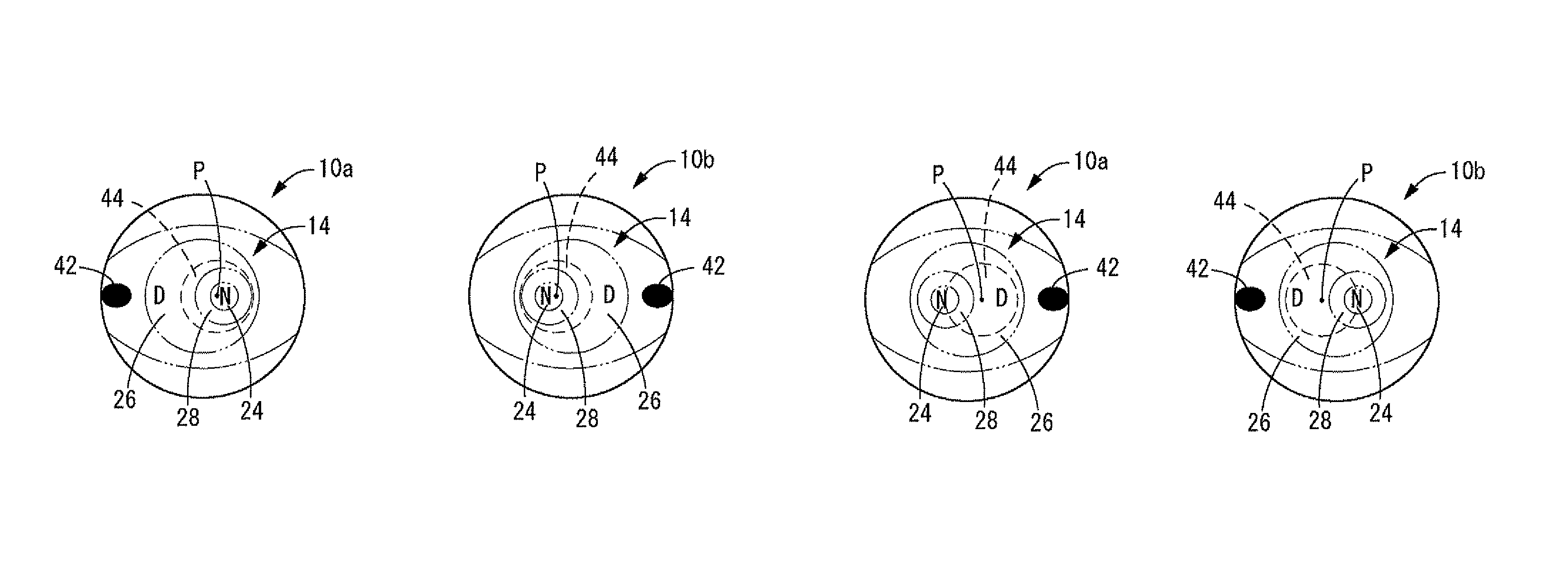
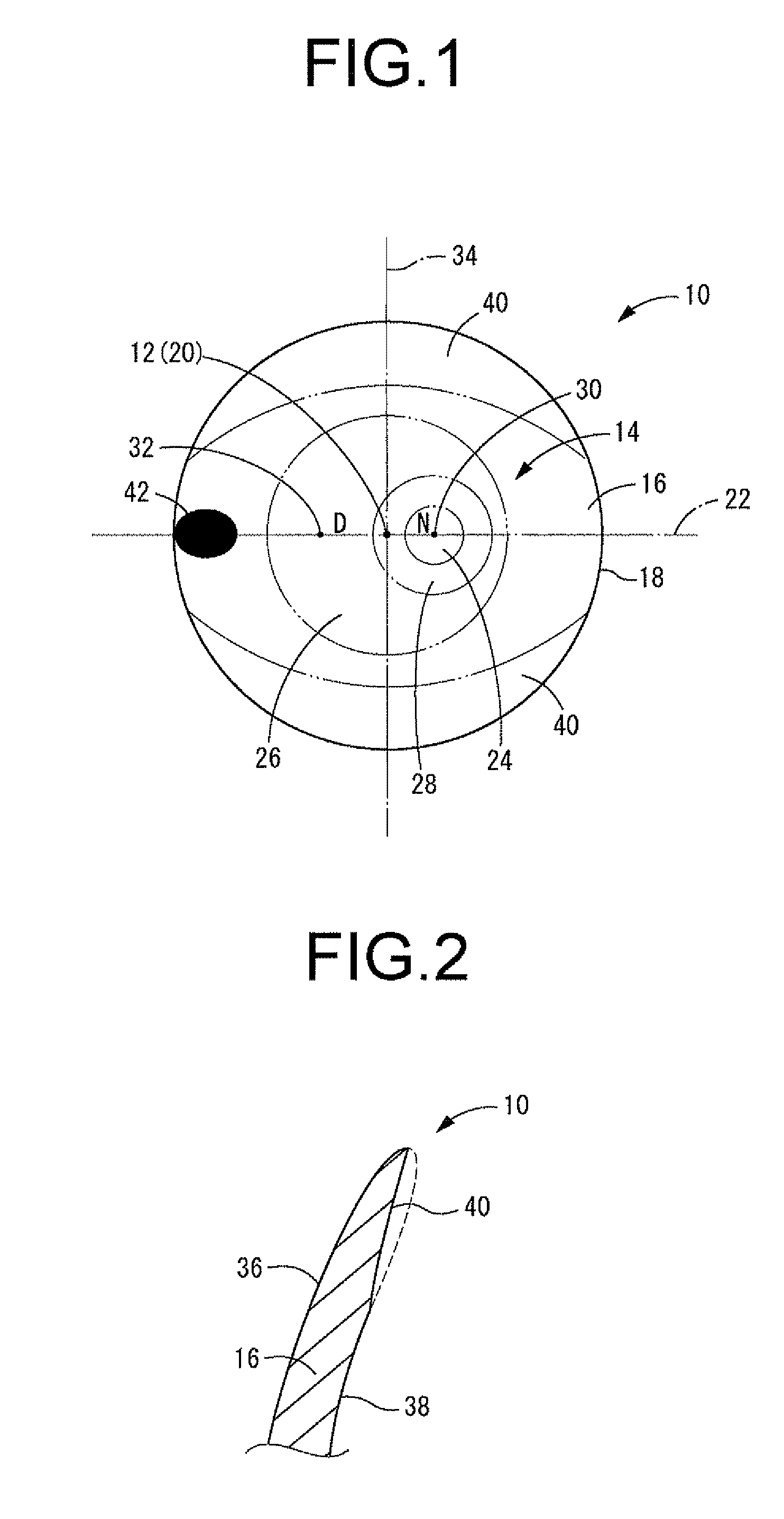
[0041]First, FIG. 1 depicts a contact lens 10 as a wearing-orientation selectable contact lens according to the present invention. As seen in front view depicted in FIG. 1, the contact lens 10 is approximately spherical shell shaped overall having the profile of a solid of revolution defined by rotation about a lens geometric center axis 12. The contact lens 10 is adapted to be worn superimposed on the surface of the cornea of the eye. In FIG. 1 and FIGS. 3A through 7 described later, the symbols “N” and “D” denote the locations of the near optical zone and the distance optical zone respectively for convenience' sake.

[0042]The contact lens 10 according to the present embodiment is a contact lens of soft type, material for which is not limited in any particular way. For example, conventional known hydrated materials such as PHEMA (polyhydroxyethyl methacrylate), PVP (polyvinyl pyrrolidone), or non-hydrated materials such as acrylic rubber, silicone could be used.

[0043]The contact len...

fourth embodiment

[0065]Next, FIG. 7 depicts a contact lens 70 as a wearing-orientation selectable contact lens according to the present invention. In the present embodiment, the optical zone geometric center axis 20 is positioned decentered from the lens geometric center axis 12 on the symmetrical meridian 22. The optical zone 14 may be positioned decentered from the lens geometric center axis 12 in this way, to an extent such that no problems are encountered during wear.

[0066]While the present invention has been shown above through certain preferred embodiments, these are merely illustrative and should not be construed as limiting the invention in any way to the specific disclosure in the embodiments.

[0067]For example, the present invention is applicable to bifocal lenses having two focal points, to multifocal lenses having more than two focal points, and to progressive multi-focal lenses. In addition, the lens does not require a distinct boundary between the first diopter power region and the seco...


PUM


Abstract

A wearing-orientation selectable contact lens including: an optical zone; a first diopter power region provided in the optical zone; and a second diopter power region having a lens power that is more positive than that of the first diopter power region. A superficial center of the second diopter power region is decentered on a symmetrical meridian from a geometric center of the optical zone. A circumferential positioning member is provided so as to selectively set up: a first stable state where the superficial center of the second diopter power region is positioned to one of left and right side of the eye, and a second stable state where the superficial center of the second diopter power region is positioned to another of left and right side of the eye. A visible indicator mark is provided for identifying a lens orientation of the first stable state and the second stable state.

Description

INCORPORATION BY REFERENCE[0001]The disclosure of Japanese Patent Application No. 2008-007114 filed on Jan. 16, 2008 including the specification, drawings and abstract is incorporated herein by reference in its entirety.BACKGROUND OF THE INVENTION[0002]1. Field of the Invention[0003]The present invention relates to a contact lens, and relates in particular to a multifocal contact lens having a plurality of diopter power regions.[0004]2. Description of the Related Art[0005]It is commonly understood that in order to correct presbyopia, for example, multifocal contact lenses such as bifocal lenses will be prescribed. These lenses include a distance region provided as a first diopter power region and a near region provided as a second diopter power region having a more positive additional diopter power than that of the distance region.[0006]For example, EP-A2-0201231 discloses such multifocal contact lenses with a configuration where a distance region and a near region are formed in a c...

Claims


Application Information

Patent Timeline
Patent Type & Authority Patents(United States)
IPC IPC(8): G02C7/04
CPCG02C7/021G02C7/043G02C7/044G02C2202/04
Inventor GOTO, YUJISAKAI, YUKIHISAYAMAGUCHI, HIROYUKI
Owner MENICON CO LTD
Why Eureka
Try Eureka