A method of manufacturing a lens for providing an optical display

A lens and optical technology, applied in optics, optical components, optical components, etc., can solve problems such as cracking, material separation, and difficulty in trimming and cutting

Active Publication Date: 2012-10-17
ESSILOR INT CIE GEN DOPTIQUE
View PDF6 Cites 10 Cited by
  • Summary
  • Abstract
  • Description
  • Claims
  • Application Information

AI Technical Summary

Problems solved by technology

The hardness of the two materials is very different, so trim cutting is very difficult, often resulting in material separation, fracture or cracking

Method used


Image

  • A method of manufacturing a lens for providing an optical display
  • A method of manufacturing a lens for providing an optical display
  • A method of manufacturing a lens for providing an optical display

Examples


Embodiment Construction

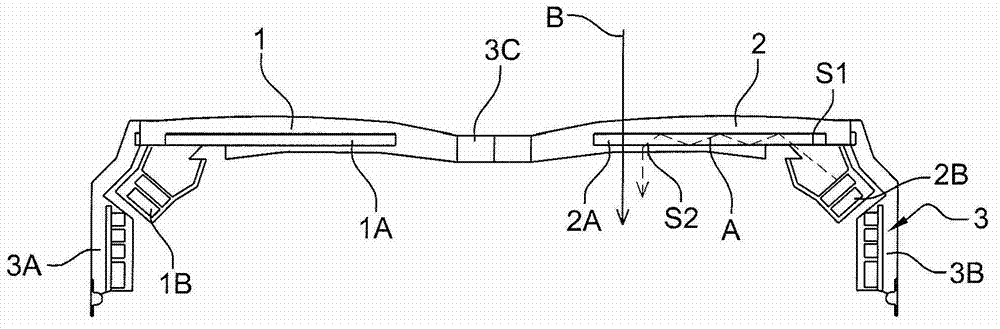
[0031] refer to figure 1 , the ophthalmic binocular display includes two lenses 1,2. Each lens includes a projection insert consisting of an optical imager 1A, 2A for shaping the beam from an electronic and optical system 1B, 2B that generates the beam based on an electronic signal, the optical system being a microscreen, Laser Diode or Light Emitting Diode type. The optical imager directs the light beam from the entering surface S 1 away from the surface S 2 directed to the wearer's eye so that the information content can be seen, as indicated by the dotted arrow A on the right lens. These lenses may allow see-through, the ambient viewport shown by arrow B on the right lens.

[0032] The lenses 1, 2 are mounted in a frame 3 for spectacles or lenses, which frame comprises two branches 3A, 3B and a nose pad 3C.

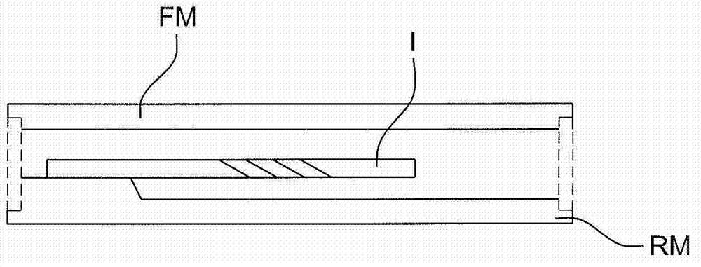
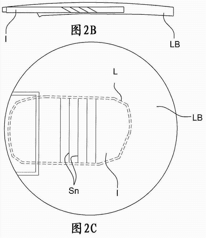
[0033] Figure 2A , 2B and 2C illustrate the method according to the first embodiment of the invention.

[0034] As described in patent document WO 2006 / 016086...


PUM

PropertyMeasurementUnit
thicknessaaaaaaaaaa
lengthaaaaaaaaaa
widthaaaaaaaaaa

Abstract

The invention concerns a method of manufacturing a lens (1, 2) that has a front face and a rear face, and into which light beams emitted by an optical element of a light beam generator system (IB) are introduced via an entry surface (Si) and directed towards the eye of the wearer to enable information content to be viewed, by means of a transparent optical insert (IA, 2A, I) constituted by a light guide, said insert (I) being with a form substantially identical to the form of a final lens suitable for being positioned in a frame (3) of a support.; According to the invention, the method comprises the following steps: manufacturing said insert (I) with a form smaller than the form of said final lens according to a proportional transformation, manufacturing a lens blank (LB) by association of plastic material forming said front face and said rear face with said insert (I) and cutting said lens blank (LB) around said insert (I) and with a distance from the edges of said insert which is around 1 mm for at least 50% of the periphery of said insert.

Description

technical field [0001] The invention relates to a lens manufacturing method for the manufacture of optical displays by optical imagers, which allows the acquisition of information by optical projection of digital images, for example of multimedia type or of data type such as GPS data. Background technique [0002] The term "lens" as used in this specification refers to an optical system especially adapted to be placed in a frame for spectacles or lenses. The term "lens" refers to a finished lens ready to be placed on a spectacle frame, or a non-finished lens or lens blank, which means that the non-finished lens or lens blank still needs to be cut, surfaced and polished by trimming so that it can be used. [0003] Patent document WO 01 / 95027 discloses a projection insert consisting of an optical imager for forming a beam from an electronic and optical system that generates a beam based on an electronic signal, which system can be a microscreen, a laser diode or Light-emitti...

Claims


Application Information

Patent Timeline
Patent Type & Authority Applications(China)
IPC IPC(8): G02B27/01B29D11/00G02C5/02
CPCB29D11/00432G02B27/0101G02C7/08G02B6/00G02C7/086B29D11/00692B29D11/00932
Inventor C·布琼G·盖里V·罗普廷A·韦德曼
Owner ESSILOR INT CIE GEN DOPTIQUE
Why Eureka
Try Eureka