
Method of video monitoring, corresponding device, system and computer programs

a video monitoring and corresponding device technology, applied in the field of digital video encoding and transmission, can solve the problems of limited functions, limited use of techniques, and limitations of detection of motion based on a comparison of frames two by two, and achieve the effect of convenient use of home video devices, simple implementation and economical effects

Inactive Publication Date: 2005-12-22
CANON EURPOPA NV
View PDF11 Cites 57 Cited by
  • Summary
  • Abstract
  • Description
  • Claims
  • Application Information

AI Technical Summary

Benefits of technology

[0013] It is another goal of the invention to implement motion detection well suited to home monitoring. In particular, it is aimed at enabling several types of monitoring, especially the detection of intruders and the monitoring of infants, in a manner that is simple to implement and economical.
[0108] means of configuring in a detection mode, called the mode for the dynamic determining of persons, making it possible to determine the presence of a person; and

Problems solved by technology

Providers of home local area network solutions propose integrated video monitoring systems, but with functions limited to permanent viewing or anti-intruder alarms (for example).
These techniques have the drawback of offering limited functions.
The detection of motion based on a comparison of frames two by two indeed entails limitations.
This technique also has the drawback of not been suited to home networks and, especially, of not being capable of redirecting an alarm towards a person who is normally present in the monitoring premises or close to them.
The different techniques have the drawback of being limited to motion detection between two frames.
Furthermore, they are relatively complex to implement and their cost is often prohibitive.
They are therefore not suited to a home network.

Method used


Image

  • Method of video monitoring, corresponding device, system and computer programs
  • Method of video monitoring, corresponding device, system and computer programs
  • Method of video monitoring, corresponding device, system and computer programs

Examples


Embodiment Construction

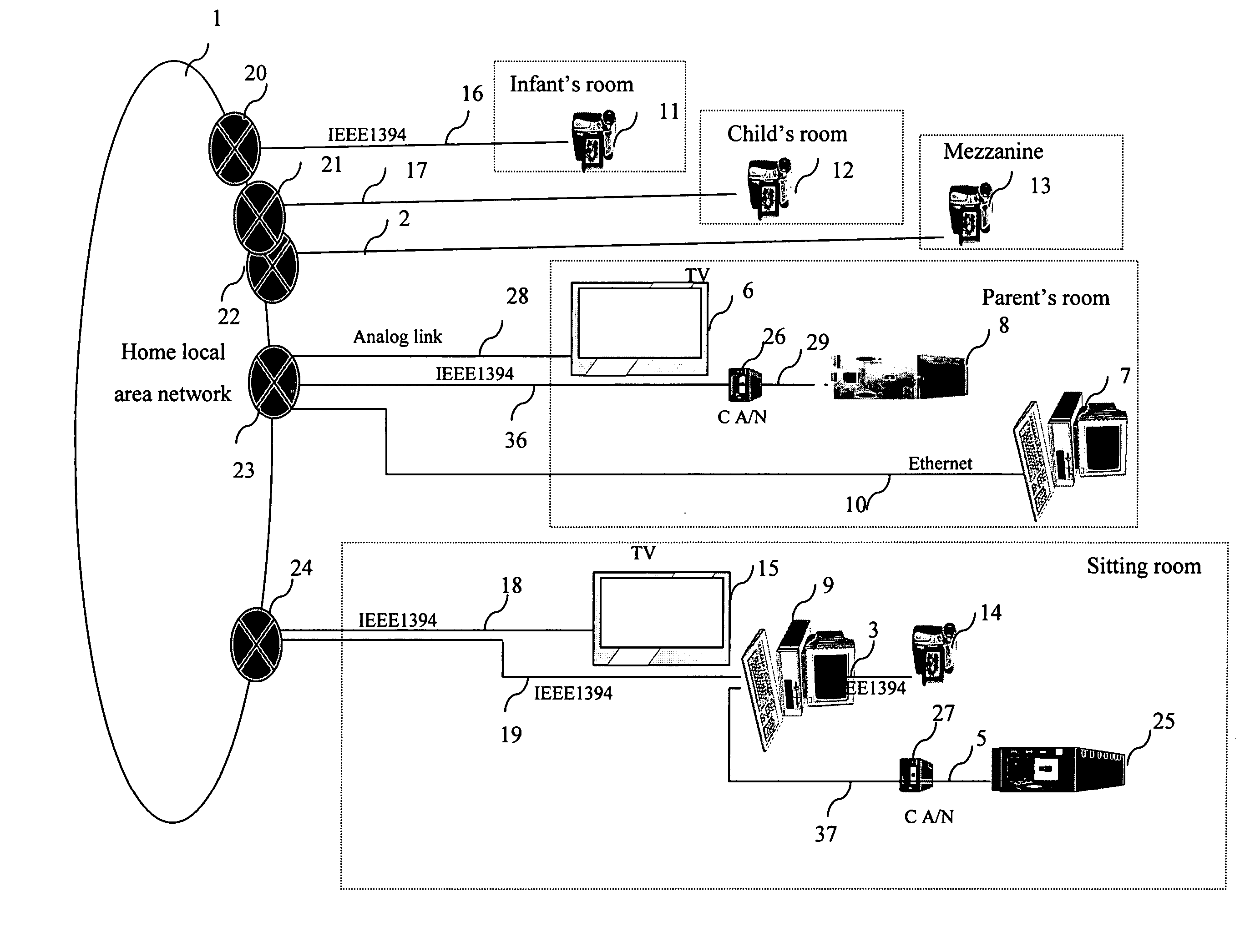
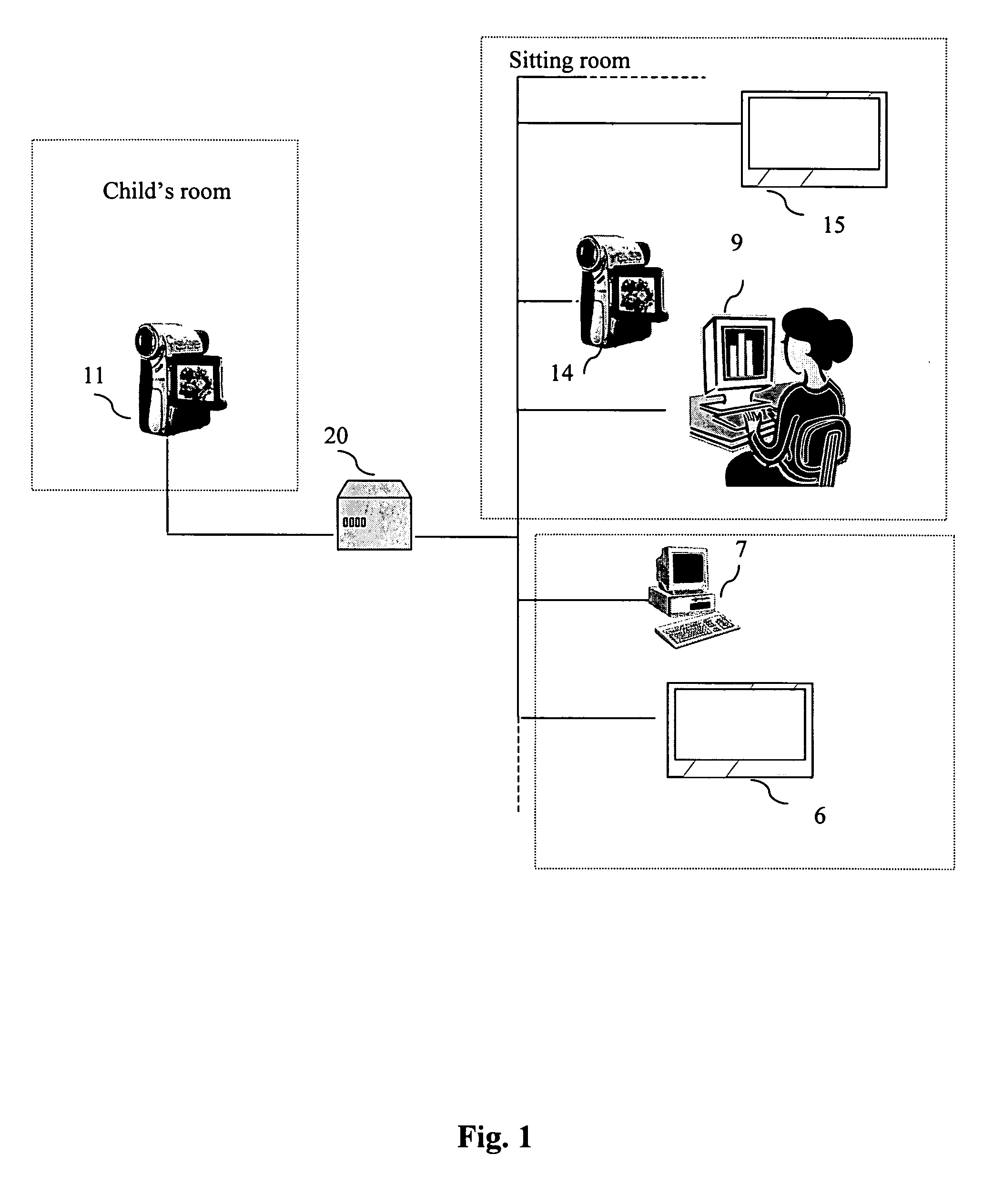
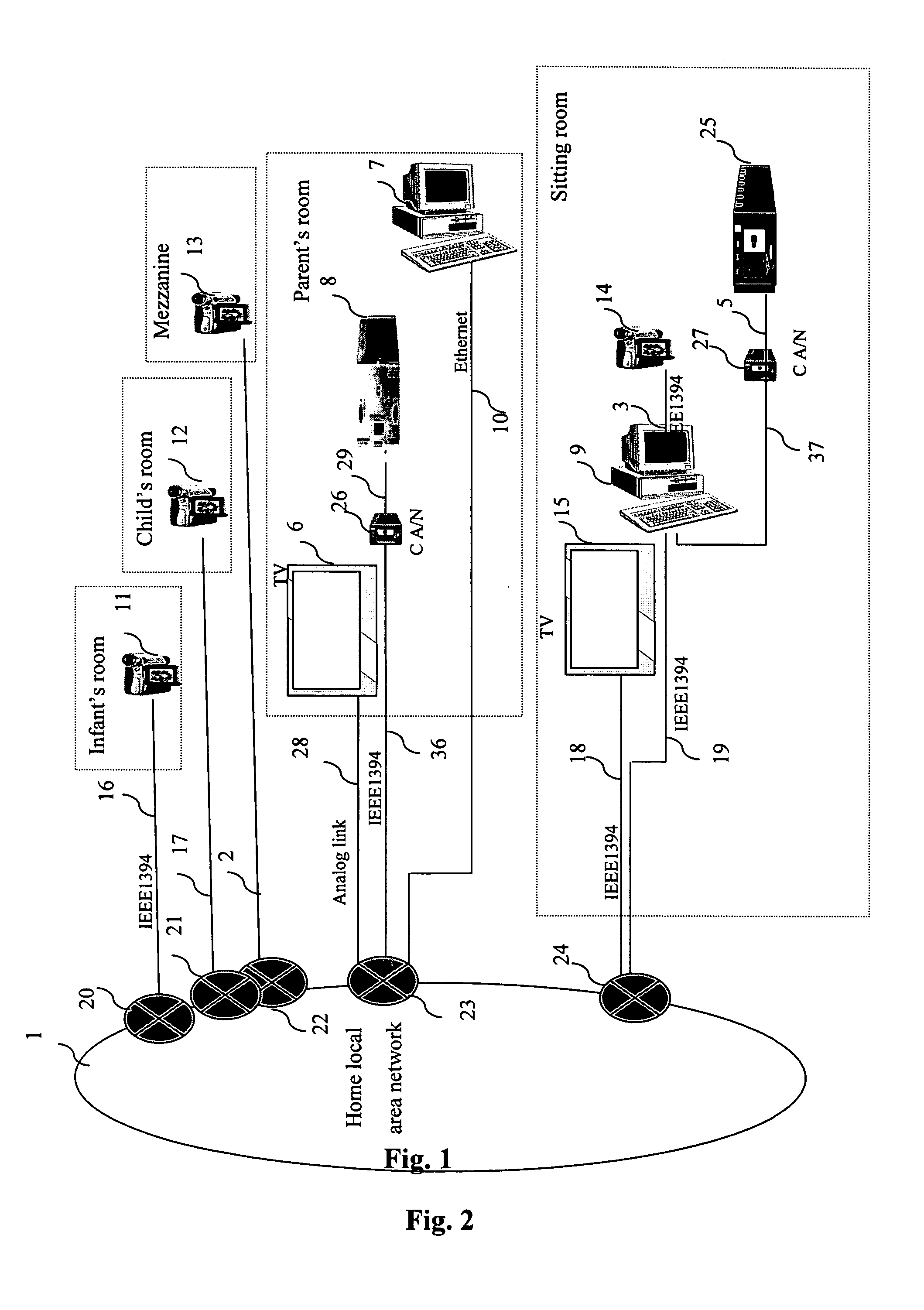
[0130] The general principle of the invention is based on a network comprising one or more cameras that transmit video streams to a node of a network working at high bit rates. This node includes means for detecting motion. This detection is done as a function of a configuration made by a user who associates each camera with a particular type of detection corresponding to a sudden motion or a slow motion with a duration of varying length. Thus, the node implements the detection by integrating the differences between two consecutive images on a detection window whose length depends on the configuration. If the totalized differences exceed an alarm threshold that is configurable, then the node memorizes the analyzed video stream and transmits a piece of visual and / or sound alarm information, and / or the corresponding video stream to a display terminal (a computer or television screen for example) enabling the user to be informed by the overlay of this data on the screen of the terminal...


PUM


Abstract

A video monitoring device, comprising: receiving means for receiving a video stream from a video source; manually operable means for setting a detection mode among at least two modes, the detection mode being solely set for the video source; motion detection means for detecting motion in the video stream in accordance with the detection mode set by said manually operable means, said motion detection means obtaining and computing a set of images from the video stream according to the detection mode; and output means for outputting the result regarding to the motion detected by said detection means.

Description

[0001] This application claims the right of priority under 35 USC § 119 based on French Patent Application number 03 12123 filed 16 Oct. 2003. 1. FIELD OF THE INVENTION [0002] The present invention relates to the field of digital video encoding and transmission. More specifically, the invention proposes a novel technique for the detection of motion, adapted to the monitoring services to be provided. 2. DESCRIPTION OF THE PRIOR ART [0003] Video monitoring or surveillance applications are very well known and widely used. Providers of home local area network solutions propose integrated video monitoring systems, but with functions limited to permanent viewing or anti-intruder alarms (for example). [0004] Many classic video monitoring systems rely on the detection of motion or presence through sensors: thus the U.S. Pat. No. 6,525,659, “Automatic sliding doors for refrigerator unit” by Jaffe et al. describes sensors detecting human presence before a door, capable of opening this door au...

Claims


Application Information

Patent Timeline
IPC IPC(8): G08B13/16G08B13/194G08B13/196H04N7/18
CPCG08B13/1672G08B13/19602G08B13/19645G08B13/19656H04N7/181G08B13/1968G08B13/19691G08B13/19695G08B21/0208G08B13/19667
Inventor CLARE, MARYLINEHENOCO, XAVIER
Owner CANON EURPOPA NV
Learn More